Measurement Computing CIO-DAS160x/1x User Manual
Page 7
3.5
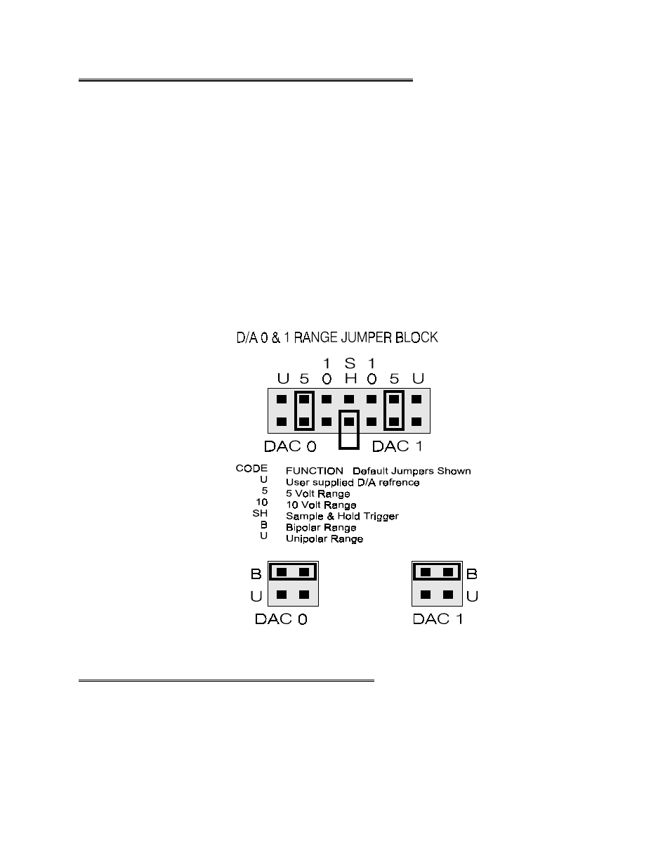
D/A CONVERTER REFERENCE JUMPER BLOCK
The jumper block located near the center of the CIO-DAS1600 allows you to use the on board precision
voltage reference to select the output ranges of the digital to analog converters.
Analog output is provided by two 12-bit multiplying D/A converters. This type of converter accepts a
reference voltage and provides an output proportional to that. The proportion is controlled by the D/A
output code (0 to 4095). Each bit represents 1/4096 of full scale.
A precision
−5V and −10V reference provide onboard D/A ranges of 0 to 5V, 0 to 10V, ±5V, ±10V.
Other ranges between 0V and 10V are available if you provide a precision voltage reference at pin 10 or
26 of the main connector.
When the DAC0 reference is supplied onboard, pin 26 of the 37 pin connector is unused and can be
employed as a simultaneous sample & hold trigger for use with the CIO-SSH16. To do so, place the
jumper between the two pins SH (Figure 3-5).
Figure 3-5. D/A Output Range Jumper Block
3.6
BIPOLAR/UNIPOLAR AND GAIN SETTING
The Bipolar or Unipolar configuration of the A/D converter is set by a switch (Figure 3-6). The switch
controls all A/D channels. Though you cannot run some channels bipolar and some unipolar, you can
measure a unipolar input in the bipolar mode. (e.g. you can monitor a 0 to 5V input with a ±5 V channel)
3