1 introduction, 2 software installation, 3 hardware installation – Measurement Computing CIO-DAS160x/1x User Manual
Page 5
1 INTRODUCTION
The installation and operation of all CIO-DAS1600 series boards are very similar. Throughout this
manual we use CIO-DAS1600 as a generic designation for the CIO-DAS1601/12, CIO-DAS1602/12, and
CIO-DAS1600/16. When required, due to the differences in the boards, the specific board name is used.
2 SOFTWARE INSTALLATION
We recommend you install and run the InstaCal
TM
installation, test and calibration utility that was
shipped with your board prior to installing the board in your computer. InstaCal
TM
will show you how to
properly set the switches and jumpers on the board prior to physically installing the board in your
computer.
Refer to the Software Installation Manual for detailed instructions regarding the installation of the
InstaCal
TM
software.
3 HARDWARE INSTALLATION
The CIO-DAS1600 has a variety of switches and jumpers to set before installing the board in your
computer. By far the simplest way to configure your board is to use the InstaCal
TM
program provided as
part of your CIO-DAS1600 software package. InstaCal
TM
will show you all available options, how to
configure the various switches and jumpers to match your application requirements, and will create a
configuration file that your application software (and the Universal Library) will refer to so the software
you use will automatically know the exact configuration of the board.
Please refer to the Software Installation Manual regarding the installation and operation of InstaCal
TM
.
The following hard copy information is provided as a matter of completeness, and will allow you to set
the hardware configuration of the CIO-DAS1600 board if you do not have immediate access to
InstaCal
TM
and/or your computer.
3.1
BASE ADDRESS
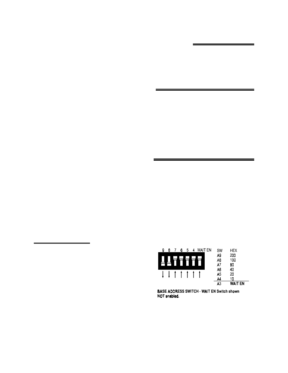
Unless there is already a board in your system using
address 300 hex (768 decimal), leave the switches as they
are set at the factory.
In Figure 3-1, the CIO-DAS1600 is set at base address
300 hex. This means the DAS-16 compatible section of
the board is at 300 hex and the DIO-24 compatible
section of the board is at 700 hex.
Figure 3-1. Base Address & Wait EN Switch
Note: Wait State Enable is typically not required. Leave the WAIT EN switch in the UP (not enabled)
position
1