Measurement Computing CIO-DAS160x/1x User Manual
Page 30
6.1.9
PROGRAMMABLE GAIN CONTROL REGISTER / BURST RATE
BASE ADDRESS + Bh
G0
G1
X
X
X
X
X
X
0
1
2
3
4
5
6
7
BURST RATE is fixed at: CIO-DAS1600/12 = 4
µs (250 kHz) between burst samples.
CIO-DAS1602/16 = 13.3
µs between burst samples (75 kHz).
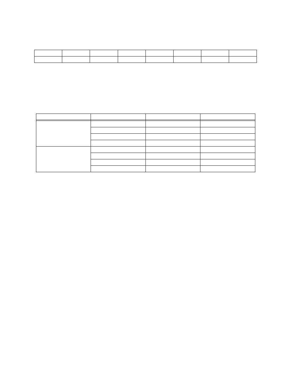
PROGRAMMABLE GAIN CONTROL: Range and gain is controlled by bits G1 and G0. The codes
have different meaning for each board in the DAS1600 family (Table 6-4).
Table 6-4. Range Codes
0 to 1.25V
+/-1.25V
3
0 to 2.5V
+/-2.5V
2
0 to 5V
+/-5V
1
0 to 10V
+/-10V
0
CIO-DAS1602/12
and
CIO-DAS1602/16
0 to 0.01V
+/-0.01V
3
0 to 0.1V
+/-0.1V
2
0 to 1V
+/-1V
1
0 to 10V
+/-10V
0
CIO-DAS1601/12
UNIPOLAR RANGE
BIPOLAR RANGE
CODE
BOARD
The range, unipolar or bipolar is controlled by a switch. If your application is better served by
programmable ranges, please consider the CIO-DAS16/Jr or CIO-DAS16/330 boards.
DT-CONNECT NOTE:
To guarantee that DT-Connect is properly initialized prior to any A/D transfer, the DT-Connect
DT-Request handshake line is reset each time this register is written to. Therefore, it is not possible to
use the DT-Connect for A/D sets which involve setting the gain between samples. This is not really a
problem because any such scheme would be low speed and therefore store data to disk, obviating the
need to use DT-Connect to store data on the MEGA-FIFO.
26