8 analog electronics, 1 voltage dividers – Measurement Computing CIO-DAS160x/1x User Manual
Page 36
8 ANALOG ELECTRONICS
8.1
VOLTAGE DIVIDERS
If you wish to measure a signal which varies over a range greater than the input range of an analog or
digital input, a voltage divider can drop the voltage of the input signal to the level the analog or digital
input can measure.
A voltage divider applies Ohm's law, which states,
Voltage = Current * Resistance ( V = I * R)
and Kirkoff's voltage law which states,
The sum of the voltage drops around a circuit will be equal to the
voltage drop for the entire circuit.
Implied in the above is that any variation in the voltage drop for the circuit as a whole will have a
proportional variation in all the voltage drops in the
circuit.
A voltage divider takes advantage of the fact that the
voltage across one of the resistors in a circuit is
proportional to the voltage across the total resistance in
the circuit.
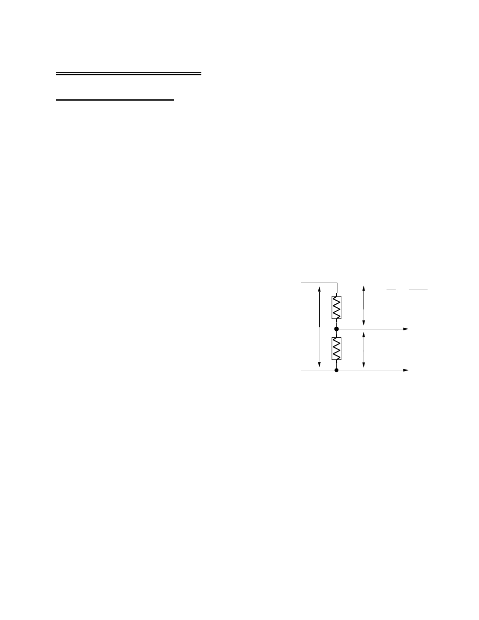
The object in using a voltage divider is to choose two
resistors with the proper proportions relative to the full
scale of the analog or digital input and the maximum
signal voltage (Figure 8-1).
Figure 8-1. Voltage Divider Schematic
Reducing a voltage proportionally is called attenuation. The formula for attenuation is:
R1 + R2
The variable Attenuation is the
Attenuation = -------- proportional difference between the
R2 signal voltage max and the full scale of the analog input.
10K + 10K
2 = ----------
For example, if the signal varies
10K
between 0 and 20 volts and you wish to measure that with an analog
input with a full scale range of 0 to 10 volts, the Attenuation is 2:1 or
just 2.
R1 = (A - 1) * R2
For a given attenuation, pick a handy resistor and call it R2, then use this
formula to calculate R1.
32
SIGNAL HIGH
SIGNAL LOW
R1
R2
A/D BOARD
HIGH INPUT
A/D BOARD
LOW INPUT
SIGNAL
VOLTS
V1
V2
Vout
Vin
=
R1 + R2
R2
SIMPLE VOLTAGE DIVIDER
Vin
Vout