Measurement Computing CIO-DAS160x/1x User Manual
Page 29
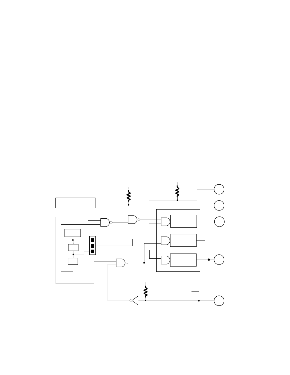
BL3 to BL0 = BURST LENGTH. This nibble determines the number of conversions per trigger when in
the burst mode. There are one to sixteen samples (single-ended) or eight samples (differential) in a burst.
When the CIO-DAS1600 is not in the burst mode these bits have no function.
CTR0 = 1. When CTR0 = 1, an onboard 100 kHz clock signal is ANDed with the COUNTER 0 CLOCK
INPUT (pin 21). A high on pin 21 will allow pulses from the onboard source into the 8254 Counter 0
input. (This input has a pull-up resistor on it, so no connection is necessary to use the onboard clock as a
pacer clock.
CTR0 = 0. When CTR0 = 0, the input to 8254 Counter 0 is entirely dependent on pulses at pin 21,
COUNTER 0 CLOCK INPUT.
TRIG0 = 1. When TRIG0 = 1 external gating of the pacer clock at pin 25 is enabled. Pin 25 going high
will enable the pacer. The input at pin 25 is connected to a pull-up resistor and will remain high unless
pulled low externally.
TRIG0 = 0. When TRIG0 = 0, the gating of the pacer clock at pin 25 is disabled. The gates of counter 1
& 2 are held high, preventing external control of the pacer gate.
Figure 6-1 may help you understand these registers. They are further explained in literature covering the
8254.
Figure 6-1. Pacer Clock Block Diagram
25
2
C O U N T E R 0
2 0
C O U N T E R 2
C O U N T E R 1
A /D PA C E R
2 5
2 4
+ 5 V
1 0 K
2 1
+ 5 V
1 0 K
1 0 M H z
1 /1 0
1 /1 0
C O N T R O L R E G IS T E R
B A S E + 1 0
T R IG
C T R 0
G AT E
G AT E
G AT E
O U T
O U T
O U T
1 0 M H z
1 M H z
+ 5 V
1 0 K
CIO-DAS1600 8254 PACER CLOCK & CONTROL
C T R 2 O U T
C T R 0 O U T
T R IG G E R
G AT E 0
C T R 0 IN