D iffe rential inp ut – Measurement Computing CIO-DAS160x/1x User Manual
Page 14
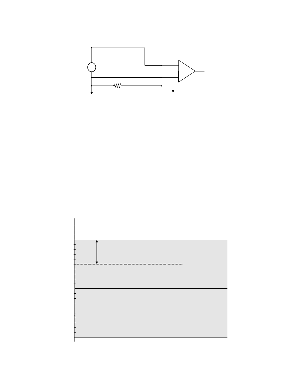
Figure 5-2b. Differential Input Theory
Before moving on to the discussion of grounding and isolation, it is important to explain the concepts of
common mode, and common mode range (CM Range). Common mode voltage is depicted in the diagram
above as Vcm. Though differential inputs measure the voltage between two signals, without (almost)
respect to the either signal’s voltages relative to ground, there is a limit to how far away from ground
either signal can go. Though the CIO-DAS1600 has differential inputs, it will not measure the difference
between 100V and 101V as 1 Volt (in fact the 100V would destroy the board!). This limitation or
common mode range is depicted graphically in Figure 5-3. The CIO-DAS1600 common mode range is
+/- 10 Volts. Even in differential mode, no input signal can be measured if it is more than 10V from the
board’s low level ground (LLGND).
Figure 5-3. Common Mode Range
10
+
-
Inp ut
A m p
To A /D
D iffe rential
Inp ut
LL G ND
C H H igh
C H Low
~
Vs
Vs
Vcm
C om m on M ode Voltage (Vcm ) is ignored
by differential input configuration. How ever,
note that V cm + Vs m u st rem ain w ithin
the am plifier’s com m on m ode range of ±10V
Vcm = V g2 - V g1
g
g1
2
+1V
+2V
+3V
+4V
-10V
+5V
-9V
+6V
-8V
+7V
-7V
+8V
-6V
+9V
-5V
+10V
-4V
+11V
-3V
+12V
-2V
+13V
-1V
G ray area represe nts com m on m ode ran
B oth V + and V - m ust a lw ays rem ain w ithi
the com m on m od e range relative to L L G
V cm
W ith V cm = +5VD C,
+V s m u st be less than +5V, or the com m on m ode range will be exceed ed (>+10V )