2 low pass filters – Measurement Computing CIO-DAS160x/1x User Manual
Page 37
Digital inputs also make use of voltage dividers, for example, if you wish to measure a digital signal that
is at 0 volts when off and 24 volts when on, you cannot connect that directly to the CIO-AD digital
inputs. The voltage must be dropped to 5 volts max when on. The Attenuation is 24:5 or 4.8. Use the
equation above to find an appropriate R1 if R2 is 1K. Remember that a TTL input is 'on' when the input
voltage is greater than 2.5 volts.
IMPORTANT NOTE: The resistors, R1 and R2, are going to dissipate all the power in the divider
circuit according to the equation Current = Voltage / Resistance. The higher the value of the resistance
(R1 + R2) the less power dissipated by the divider circuit. Here is a simple rule:
For Attenuation of 5:1 or less, no resistor should be less than 10K.
For Attenuation of greater than 5:1, no resistor should be less than 1K.
The CIO-TERMINAL has the circuitry on board to create custom voltage dividers. The
CIO-TERMINAL is a 16" by 4" screw terminal board with two 37 pin D type connectors and 56 screw
terminals (12 - 22 AWG). Designed for table top, wall or rack mounting, the board provides prototype,
divider circuit, filter circuit and pull-up resistor positions which you can complete with the proper value
components for your application.
8.2
LOW PASS FILTERS
A low-pass filter is placed on the signal wires between a signal and an A/D board. It stops frequencies
greater than the cut off frequency from entering the A/D board's analog or digital inputs.
The key term in a low-pass filter circuit is cutoff frequency. The
cutoff frequency is that frequency above which no variation of
voltage with respect to time can enter the circuit. For example, if
a low-pass filter had a cutoff frequency of 30 Hz, the kind of
interference associated with line voltage (60Hz) would be
filtered out but a signal of 25 Hz would be allowed to pass.
Also, in a digital circuit, a low-pass filter might be used to
“de-bounce” an input from a momentary contact switch or a relay
closure.
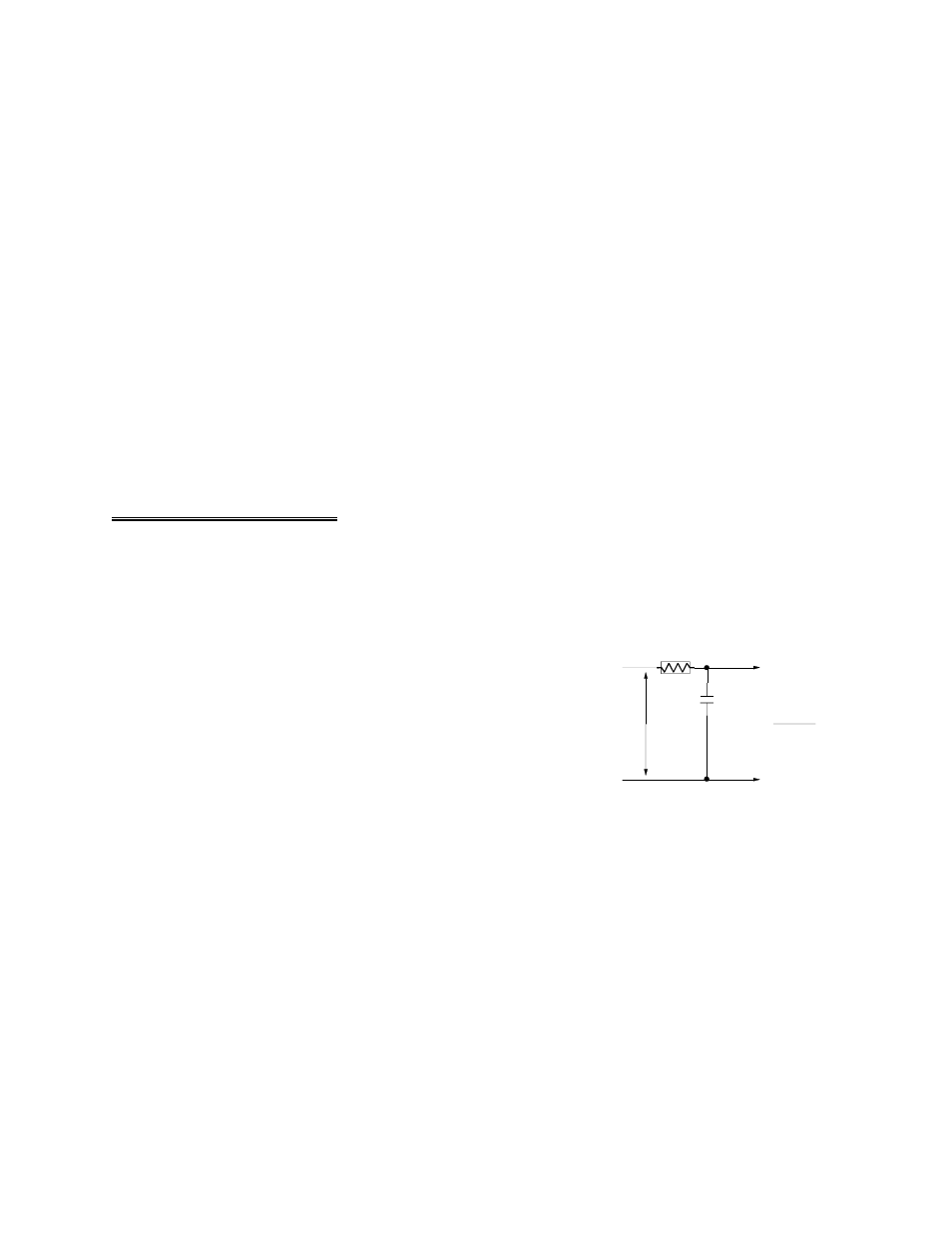
Figure 8-2. Low-Pass Filter Schematic
A simple low-pass filter (Figure 8-2) can be constructed from one resistor (R) and one capacitor (C). The
cutoff frequency is determined according to the formula:
1
Fc = --------------
2 *
π
* R * C
1
Where :
π = 3.14....
R = ----------------
R = ohms
2*
π
* C * Fc
C = farads
33
SIGNAL HIGH
SIGNAL LOW
A/D BOARD
HIGH INPUT
A/D BOARD
LOW INPUT
SIGNAL
VOLTS
LOW PASS FILTER
R
C
F
C
=
2 *P i*R *C
1