Measurement Computing CIO-DAS160x/1x User Manual
Page 26
6.1.4
FOUR BIT DIGITAL I/O REGISTERS
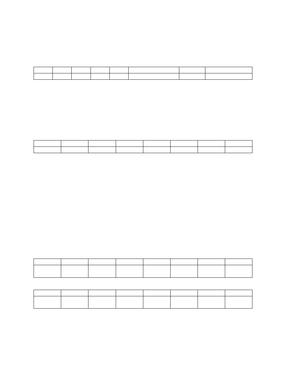
BASE ADDRESS+3
A read and write register.
When read from...
DI0, TRIG
DI1
DI2, CTR0, GATE
DI3
0
0
1
1
0
1
2
3
4
5
6
7
READ
The signals present at the inputs are read as one byte, the most significant four bits of which are always
zero. The pins 25 (digital input 0) and 24 (digital input 2) digital inputs have two functions each.
The TRIG function of digital input 0 can be used to hold off the first sample of an A/D set by holding it
low (0V) until you are ready to take samples, which are then paced by the 8254. It can also be used as
the source of an external start conversion pulse, synchronizing A/D conversions to some external event.
When written to..
DO0
DO1
DO2
DO3
X
X
X
X
0
1
2
3
4
5
6
7
WRITE
The upper four bits are ignored. The lower four bits are latched TTL outputs. Once written, the state of
the inputs cannot be read back because a read back would read the separate digital input lines (see
above).
NOTE
Since the digital inputs have multiple functions, use the digital input lines 0-3 with
care when you are also using the A/D converter.
The digital outputs are also used by the CIO-EXP32, 32-channel analog
multiplexer/amplifier.
6.1.5
D/A REGISTERS
D/A 0 REGISTERS
BASE ADDRESS +4
X
X
X
X
D/A0
LSB
D/A1
D/A2
D/A3
0
1
2
3
4
5
6
7
BASE ADDRESS + 5
D/A4
D/A5
D/A6
D/A7
D/A8
D/A9
D/A10
D/A11
MSB
0
1
2
3
4
5
6
7
22