Measurement Computing CIO-DAS160x/1x User Manual
Page 32
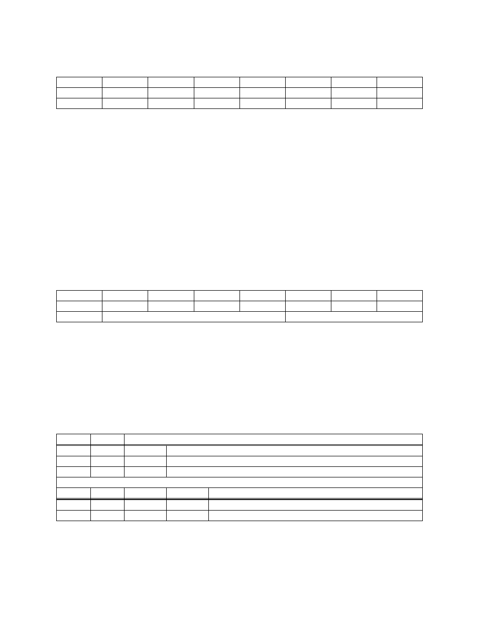
PORT C DATA
BASE ADDRESS +402h
CL0
CL1
CL2
CL3
CH0
CH1
CH2
CH3
C0
C1
C2
C3
C4
C5
C6
C7
0
1
2
3
4
5
6
7
Port C can be used as one 8-bit port of either input or output, or it can be split into two 4-bit ports which
can be independently input or output. The notation for the upper 4-bit port is CH3 - CH0, and for the
lower, CL3 - CL0.
Although it can be split, every read and write to port C carries eight bits of data so unwanted information
must be ANDed out of reads, and writes must be ORed with the current status of the other nibble.
OUTPUT PORTS
In 8255 mode 0 configuration, ports configured for output hold the output data written to them. This
output byte can be read back by reading a port configured for output.
INPUT PORTS
In 8255 mode 0 configuration, ports configured for input read the state of the input lines at the moment.
Transitions are not latched.
8255 CONTROL REGISTER
BASE ADDRESS +403h
Group B
Group A
CL
B
M1
CU
A
M2
M3
MS
0
1
2
3
4
5
6
7
The 8255 can be programmed to operate in Input/ Output (mode 0), Strobed Input/ Output (mode 1) or
Bi-Directional Bus (mode 2).
When the PC is powered up or RESET, the 8255 is reset. This places all 24 lines in Input mode and no
further programming is needed to use the 24 lines as TTL inputs.
To program the 8255 for other modes, the following control code byte must be assembled into an 8 bit
byte.
MS = Mode Set. 1 = mode set active
Output
0
0
0
0
Input
1
1
1
1
INDEPENDENT FUNCTION
CH
CL
B
A
Bi-Directional Bus
Mode 2
X
1
Strobed Input / Output
Mode 1
1
0
Input / Output
Mode 0
1
0
GROUP A FUNCTION
M2
M3
28