Measurement Computing CIO-DAS160x/1x User Manual
Page 27
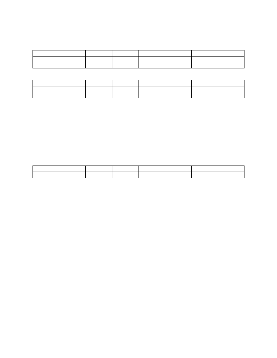
D/A 1 REGISTERS
BASE ADDRESS + 6
X
X
X
X
D/A0
LSB
D/A1
D/A2
D/A3
0
1
2
3
4
5
6
7
BASE ADDRESS + 7
D/A4
D/A5
D/A6
D/A7
D/A8
D/A9
D/A10
D/A11
MSB
0
1
2
3
4
5
6
7
WRITE ONLY
Each 12 bit D/A output line has two registers. The first contains the four least significant bits of the data
and four bits that don't care. The second register contains the eight most significant bits of the data.
The D/A will be updated when the eight most significant bits (upper register) are written. In this way,
the lower four bits can be written with no effect on the D/A output until the remainder of the data is
written to the upper eight bits.
6.1.6
STATUS REGISTER
BASE ADDRESS + 8
CH0
CH1
CH2
CH3
INT
MUX
U/B
EOC
0
1
2
3
4
5
6
7
A read mostly, one-function-write register.
READ
EOC = 1, the A/D converter is busy. EOC = 0, it is free.
U/B = 1, the amplifier is in Unipolar mode. U/B = 0, is bipolar.
MUX = 1, Channels are configured 16 single ended. MUX = 0, 8 differential.
INT = 1, an interrupt has been received. INT = 0, ready to receive an interrupt. An interrupt service
routine must clear this bit after each interrupt.
CH3, CH2, CH1 & CH0 are a binary number between 0 and 15 indicating the MUX channel currently
selected and is valid only when EOC = 0. The channel MUX increments shortly after EOC = 1 so may
be in a state of transition when EOC = 1.
WRITE
A write of any data to this register sets the INT bit to 0.
23