Measurement Computing CIO-DAS160x/1x User Manual
Page 11
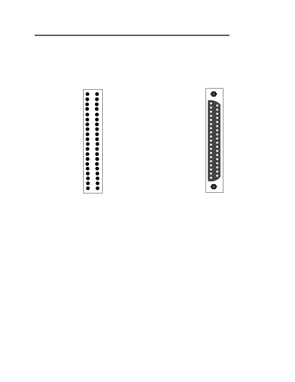
4.2
DIGITAL I/O CONNECTOR (NOT APPLICABLE TO -P5 VERSIONS)
The digital I/O connector is mounted at the rear of the CIO-DAS1600 and will accept a 40-pin header
connector. The optional BP40-37 cable assembly brings the signals to a back plate with a 37-pin male
connector mounted in it. When connected through the BP40-37, the CIO-DAS1600 digital connector is
identical to the CIO-DIO24 connector. The pin out of the 40- pin digital connector and the BP40-37 cable
assembly are shown in Figure 4-2 below.
Figure 4-2. Digital 40-Pin Connector Pinout - BP40-37 Cable Assembly to Back Panel Pinout
7
P O R T A 0
P O R T A 1
P O R T A 2
P O R T A 3
P O R T A 4
P O R T A 5
P O R T A 6
P O R T A 7
P O R T C 0
P O R T C 1
P O R T C 2
P O R T C 3
P O R T C 4
P O R T C 5
P O R T C 6
P O R T C 7
G N D
+ 5V
37
36
35
34
33
32
31
30
29
28
27
26
25
24
23
22
21
20
19
18
17
16
15
14
13
12
11
10
9
8
7
6
5
4
3
2
1
G N D
+ 5V
G N D
N C
G N D
N C
G N D
N C
G N D
P O R T B 0
P O R T B 1
P O R T B 2
P O R T B 3
P O R T B 4
P O R T B 5
P O R T B 6
P O R T B 7
N C
N C
39 NC
37 GND
35 +5V
33 GND
31 NC
29 GND
27 NC
25 GND
23 NC
21 GND
19 PORT B0
17 PORT B1
15 PORT B2
13 PORT B3
11 PORT B4
9
PORT B5
7
PORT B6
5
PORT B7
3
NC
1 NC
NC 40
NC 38
PORT A0 36
PORT A1 34
PORT A2 32
PORT A3 30
PORT A4 28
PORT A5 26
PORT A6 24
PORT A7 22
PORT C0 20
PORT C1 18
PORT C2 16
PORT C3 14
PORT C4 12
PORT C5 10
PORT C6 8
PORT C7 6
GND 4
+5V 2