Default configuration – Measurement Computing SC-1608 Series User Manual
Page 6
SC-1608 Series User's Guide
About this User's Guide
6
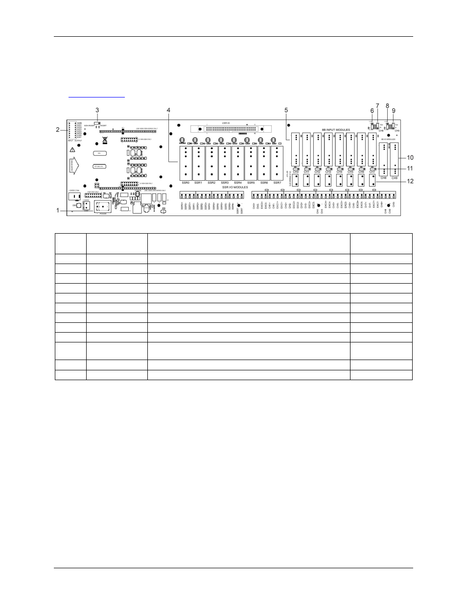
Default configuration
Each SC-1608 Series product has switches and jumpers on the baseboard that should be configured before use.
Refer to Figure 1 and the table below list the location and default setting of each configurable item. Refer to the
chapter on page 14 for more information about each item.
Figure 1. Configurable component locations
Callout Designation
Description
Default
Configuration
1
SW1 (POWER)
Power switch
Off
2
SW2
8-position DIP switch for SSR module direction
All OUTPUT
3
W1
Non-invert/Invert logic control jumper
INVERT
4
SSR0 to SSR7
Mounting locations for SSR digital I/O modules
Unpopulated
5
CH0 to CH7
Mounting locations for 8B input modules
Unpopulated
6
J30
AOUT0 voltage divider for module location CH8 (U9)
±10 V
7
J29
AOUT0 readback or convert location CH8 (U9) to input
OUT (no function)
8
J32
AOUT1 voltage divider for module location CH9 (U10)
±10 V
9
J31
AOUT1 readback or convert location CH9 (U10) to input
OUT (no function)
10
CH8 to CH9
Mounting locations for 8B I/O modules (analog voltage input or
voltage/current output)
Unpopulated
11
J21 to J28
CJC Enable jumpers
All Disabled
12
R1 to R8
Resistor locations
Unpopulated