Usb-1608g-oem series connectors (j5/j6) – Measurement Computing SC-1608 Series User Manual
Page 31
SC-1608 Series User's Guide
Specifications
31
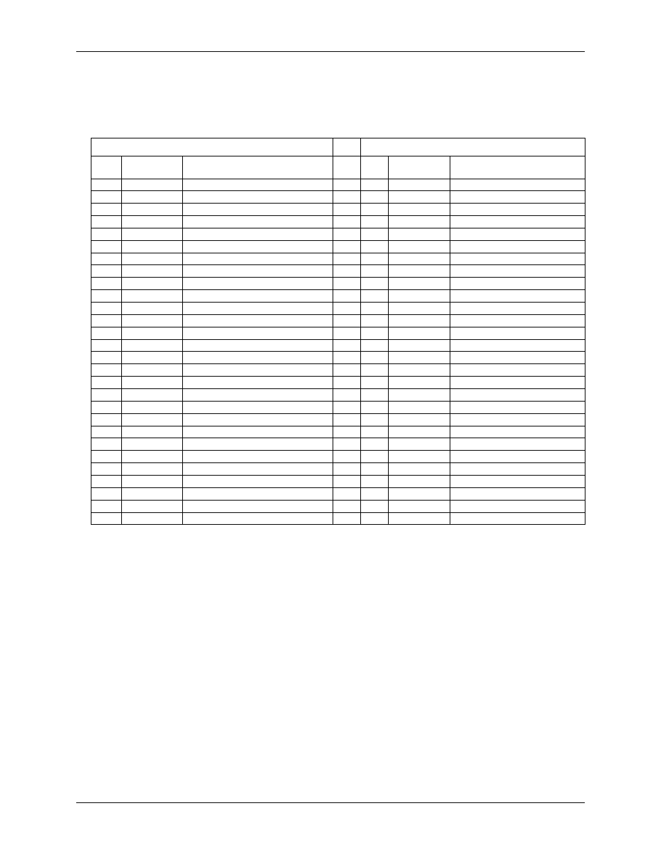
USB-1608G-OEM Series connectors (J5/J6)
Use these connectors to mate with a USB-1608G-OEM Series board.
Table 12. J5/J6 connector pinout
J5
J6
Pin
Signal
name
Pin description
Pin
Signal
name
Pin description
1
CH0
Analog input 0 (single-ended)
1
CH15
Analog input 15 (single-ended)
2
CH8
Analog input 8 (single-ended)
2
CH7
Analog input 7 (single-ended)
3
GND
Ground
3
GND
Ground
4
CH1
Analog input 1 (single-ended)
4
CH14
Analog input 14 (single-ended)
5
CH9
Analog input 9 (single-ended)
5
CH6
Analog input 6 (single-ended)
6
GND
Ground
6
GND
Ground
7
CH2
Analog input 2 (single-ended)
7
CH13
Analog input 13 (single-ended)
8
CH10
Analog input 10 (single-ended)
8
CH5
Analog input 5 (single-ended)
9
GND
Ground
9
GND
Ground
10
CH3
Analog input 3 (single-ended)
10
CH12
Analog input 12 (single-ended)
11
CH11
Analog input 11 (single-ended)
11
CH4
Analog input 4 (single-ended)
12
GND
Ground
12
GND
Ground
13
AOUT0
Analog output 0 (Note 14)
13
GND
Ground
14
GND
Ground
14
GND
Ground
15
AOUT1
Analog output 1 (Note 14)
15
+VO
+5 V output
16
GND
Ground
16
GND
Ground
17
17
18
GND
Ground
18
GND
Ground
19
DIO0
DIO bit 0
19
AICKI
AI clock input
20
DIO1
DIO bit 1
20
AICKO
AI clock output (Note 14)
21
DIO2
DIO bit 2
21
AOCKI
AI clock input
22
DIO3
DIO bit 3
22
AOCKO
AO clock output (Note 14)
23
DIO4
DIO bit 4
23
TRIG
Trigger input
24
DIO5
DIO bit 5
24
GND
Ground
25
DIO6
DIO bit 6
25
CTR1
Counter 1 input
26
DIO7
DIO bit 7
26
CTR0
Counter 0 input
27
GND
Ground
27
TMR
Timer output
28
NC
Do not connect
28
GND
Ground
Note 14:
AOUT0/AOUT1 and AICKO/AOCKO have no function when the SCC-8-8-2 is connected to
an OEM DAQ board with no analog output capability, such as the USB-1608GX-OEM or
USB-1608G-OEM.