8b analog i/o module control jumpers, Jumpers j29 and j31, 8b analog i/o module – Measurement Computing SC-1608 Series User Manual
Page 19: Control jumpers, Analog i/o module control jumpers
SC-1608 Series User's Guide
Functional Details
19
Shunt resistors are user-supplied
If installing a shunt resistor, we recommend using a Dataforth SCM7BXR1 250 Ω current conversion resistor.
Contact Dataforth for the specification.
8B analog I/O module control jumpers
Jumpers
J29
and
J31
are associated with the module installed in location CH8 (U9). Jumpers
J30
and
J32
are
associated with the module installed in CH9 (U10). Module locations CH8 and CH9 are wired by default for
output.
J29 and J30 can be used to convert an output location to input (this requires a board without AOUT
functionality), or to measure the analog output voltage being applied to the output module's input pin.
J30 and J32 are voltage divider jumpers used to scale the analog output voltage to match the output voltage
range of the installed module. These jumpers require that an output module be installed, and have no effect
when an input module is installed.
Jumpers J29 and J31
The following table lists the configuration options for the 8B output control jumpers J29 and J31.
Jumper J29 (location CH8) and J31 (location CH9) configuration
J29/31
jumper
position
Function
1-2
(default)
No function
2-3
output module
installed in
CH8 (U9) or
CH9 (U10)
This configuration lets you measure (read back) the value of the analog output voltage at the
header connector.
J29: connects OEM DAQ board output channel AOUT0 to the OEM DAQ board input channel
CH8 (J35 pin 13), or converts 8B I/O module location CH8 (U9) to an 8B input module
location.
J31: connects OEM DAQ board output channel AOUT1 to the OEM DAQ board input channel
CH9 (J35 pin 14), or converts 8B I/O module location CH9 (U10) to an 8B input module
location.
Note: When using the SC-1608X-2AO-USB, you can read back the AOUTx voltage from the
CH8/CH9 pins on the J35 header. When using the SC-1608-2AO-ENET, you can read back the
AOUTx voltage from J35 pins 25 and 27 using a voltmeter or other DAQ board.
2-3
input module
installed in
CH8 (U9) or
CH9 (U10)
This configuration converts the default output module location to input.
J29: converts module location CH8 to an input location.
J31: converts module location CH9 to an input location.
Note: Voltage input modules installed in CH8 or CH9 must be 2-wire types that don’t require
excitation terminals.
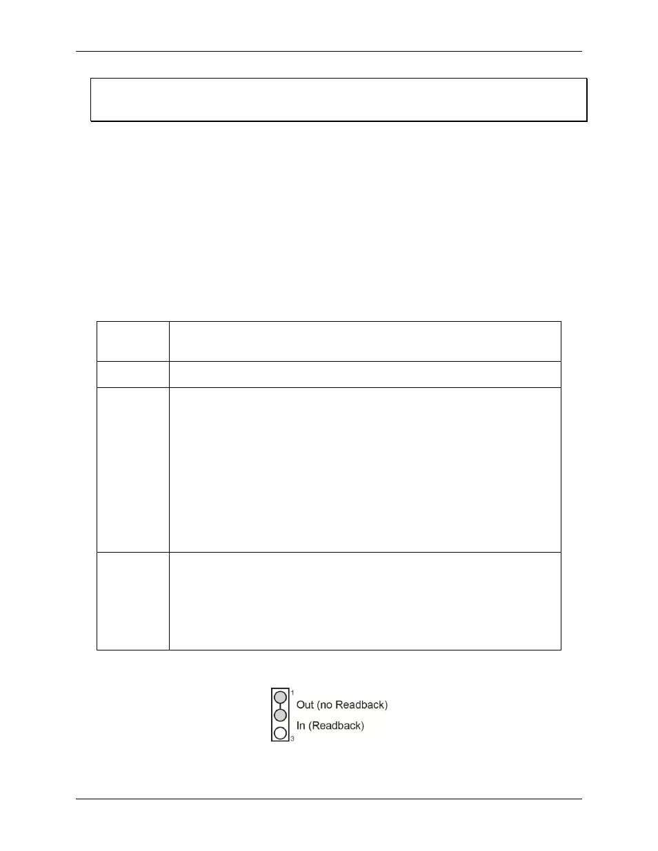
Figure 9 shows jumper 29 and 31 set for its default configuration. This jumper has no function when set to the
default 1-2 position.
Figure 9. Jumper 29 and J31 default configuration (no function)