Power switch, E-1608-oem connectors, Usb-1608g-oem series connectors – Measurement Computing SC-1608 Series User Manual
Page 15: Pin user i/o header connector
SC-1608 Series User's Guide
Functional Details
15
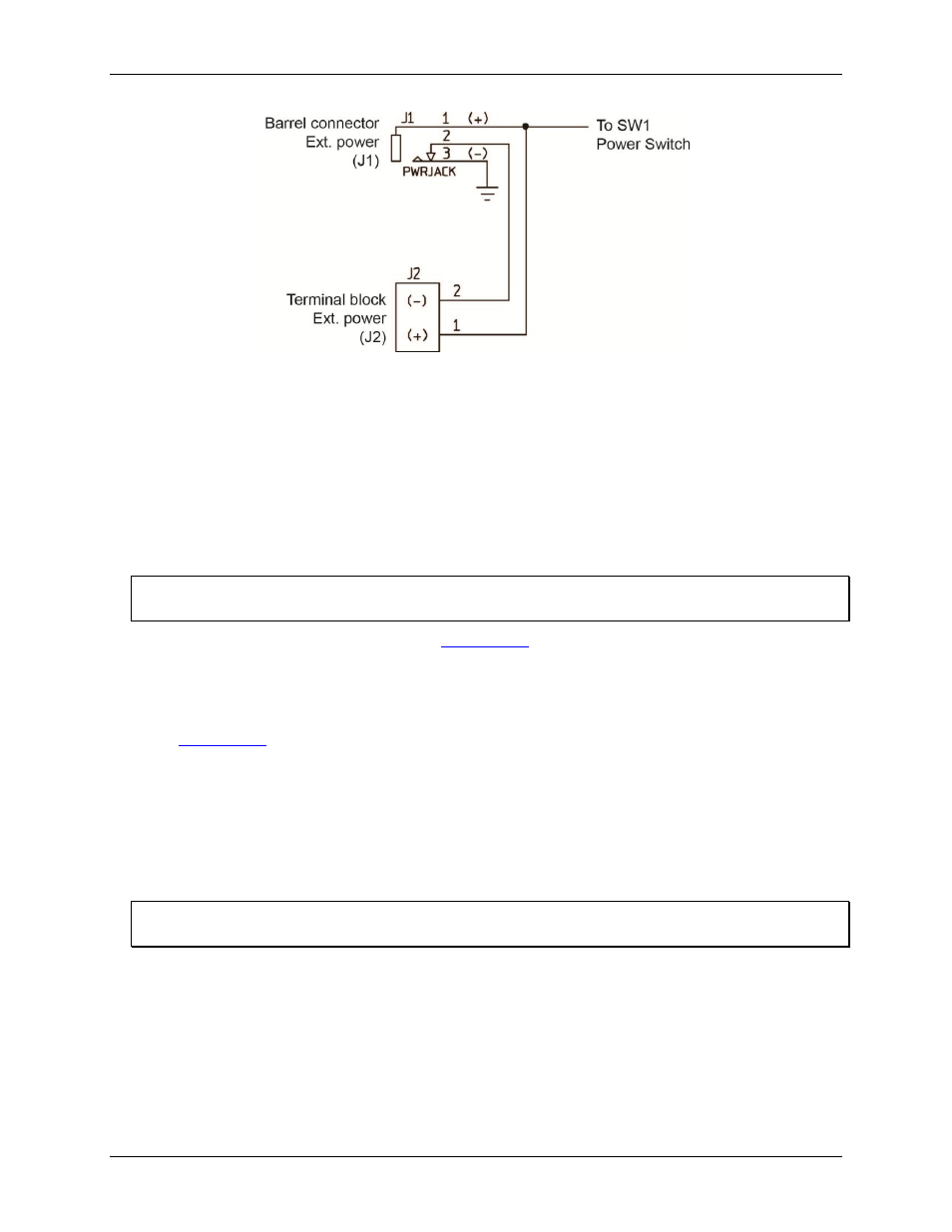
Figure 5. J1 and J2 power schematic
Power switch
SW1
is the main power switch that provides power to the baseboard when it is switched on and when an
external supply is connected to either
J1
or
J2
.
E-1608-OEM connectors
Socket connectors
J3
and
J4
connect with the header connectors on an E-1608-OEM board.
The
J37
header connector is used to power the E-1608-OEM. When the E-1608-OEM connects to the
baseboard, its power input header (
W1
) mates with the baseboard power header connector (
J37
).
The E-1608-OEM receives power from the SCC-8-8-2 baseboard
Do not connect an external supply to the E-1608-OEM barrel input connector.
Pinout tables for J3, J4, and J37 are listed in the
USB-1608G-OEM Series connectors
Socket connectors
J5
and
J6
connect with the header connectors on a USB-1608G-OEM Series board. The
connectors are keyed to ensure proper board orientation. Pinout tables for socket connectors J5 and J6 are listed
in the
50-pin User I/O header connector
J35
is a 50-pin header connector where all conditioned and non-conditioned input and output signals are
available for user connections.
The eight analog inputs, two analog outputs, and eight digital I/O that interface with the 8B analog I/O modules
and digital I/O modules are connected directly to this header connector. Any non-conditioned input or output
can be used as a non-isolated channel.
Do not connect to a signal being used by an analog or digital module
Be careful not to connect to a signal already in use by a digital I/O or analog I/O module.