Connector cabling and signal termination, Ssr i/o module input/output type dip switch – Measurement Computing SC-1608 Series User Manual
Page 16
SC-1608 Series User's Guide
Functional Details
16
The following table lists the pinout for header connector
J35
.
J35 connector pinout
Pin
Signal
name
Pin description
Pin
Signal
name
Pin description
1
CH0
Analog input 0 (single-ended)
2
CH1
Analog input 1 (single-ended)
3
CH2
Analog input 2 (single-ended)
4
CH3
Analog input 3 (single-ended)
5
GND
Ground
6
GND
Ground
7
CH4
Analog input 4 (single-ended)
8
CH5
Analog input 5 (single-ended)
9
CH6
Analog input 6 (single-ended)
10
CH7
Analog input 7 (single-ended)
11
GND
Ground
12
GND
Ground
13
CH8
Analog input 8 (single-ended)
14
CH9
Analog input 9 (single-ended)
15
CH10
Analog input 10 (single-ended)
16
CH11
Analog input 11 (single-ended)
17
GND
Ground
18
GND
Ground
19
CH12
Analog input 12 (single-ended)
20
CH13
Analog input 13 (single-ended)
21
CH14
Analog input 14 (single-ended)
22
CH15
Analog input 15 (single-ended)
23
GND
Ground
24
GND
Ground
25
AOUT0
Analog output 0
26
GND
Ground
27
AOUT1
Analog output 1
28
GND
Ground
29
+VO
+5V user output
30
GND
Ground
31
GND
Ground
32
GND
Ground
33
DIO0
DIO bit 0
34
DIO1
DIO bit 1
35
DIO2
DIO bit 2
36
DIO3
DIO bit 3
37
DIO4
DIO bit 4
38
DIO5
DIO bit 5
39
DIO6
DIO bit 6
40
DIO7
DIO bit 7
41
AICLKI
AI clock input
42
AICLKO
AI clock output
43
AOCLKI
AO clock input
44
AOCLKO
AO clock output
45
TRIG
Trigger Input
46
GND
Ground
47
CTR0
Counter 0 Input
48
CTR1
Counter 1 input
49
TMR
Timer Output
50
GND
Ground
Analog input signals CH8 to CH15 have no function when the E-1608-OEM is connected. Analog output
signals AOUT0 and AOUT1 and AOCLKO have no function when a USB-1608G-OEM or USB-1608GX-
OEM is connected.
Connector cabling and signal termination
The User I/O connector is compatible with C50FF-x ribbon cable and CIO-MINI50 screw terminal board.
Details on these accessories are available on our website.
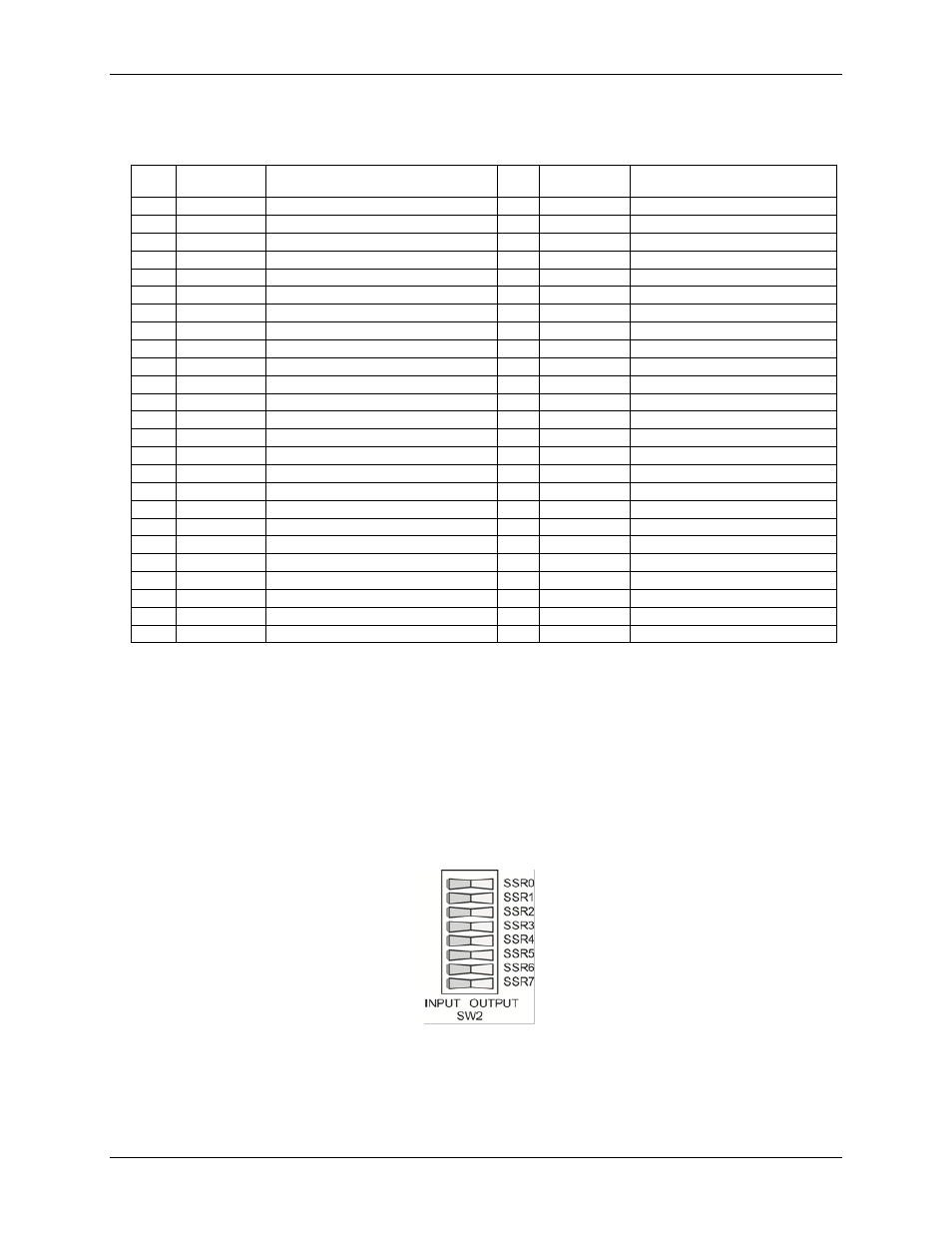
SSR I/O module input/output type DIP switch
Switch
SW2
is an 8-position DIP switch used to set the module type for each installed SSR module as either
input or output. Each DIP switch position is set by default for OUTPUT. Switch
SW2
is shown in Figure 6.
Figure 6. I/O module type DIP switch SW2
Push down on the left side to set the DIP switch position for input; push down on the right side to set the DIP
switch position for output.