Non-invert/invert logic control jumper, Digital i/o module mounting locations, Digital i/o module leds – Measurement Computing SC-1608 Series User Manual
Page 17: Digital i/o module screw terminals
SC-1608 Series User's Guide
Functional Details
17
Set SW2 to INPUT for use with digital input modules. Set to OUTPUT for use with digital output modules.
You set the digital direction of the OEM DAQ board digital channels with software. SW2 switches have no
effect on the bit direction of the digital I/O channels on the OEM DAQ board.
When a switch position is set for output, the behavior of the associated digital module is affected by the
configuration of the invert logic jumper (
W1
) and the digital logic state of the OEM DAQ board. Module
behavior for each configuration is summarized in the
section on page 23.
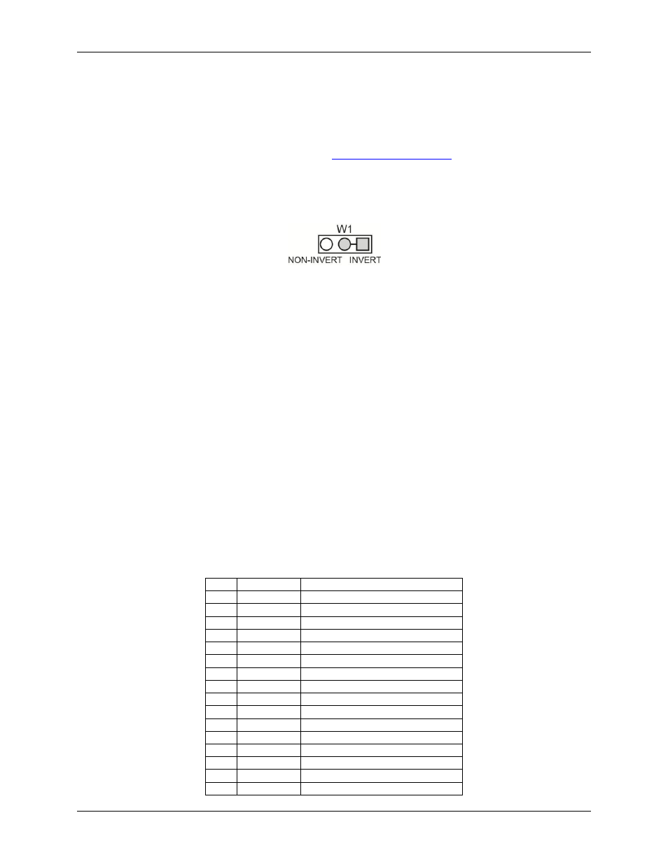
Non-invert/Invert logic control jumper
Jumper
W1
sets the control logic polarity for each digital output module installed in locations
SSR0
-
SSR7
to
inverted logic (active high, default) or non-inverted (active low). Figure 7 shows
W1
set for inverted logic.
Figure 7. Switch S2 default configuration
The invert/non-invert setting applies only to output modules, and has no effect on input modules. When a
switch position is set for output, the associated output module behavior is determined by the configuration of
the invert logic control jumper (
W1
) and the digital logic state set for the OEM DAQ board digital bits. The
logic table on page 23 summarizes module behavior for each configuration.
Digital I/O module mounting locations
You can install up to eight digital I/O modules into mounting locations
SSR0
to
SSR7
. Supported modules are
listed on page 9. Set the module input/output type for each installed module with onboard switch
SW2
.
Digital I/O module LEDs
Each digital I/O module has an associated LED. For digital output modules, the LED turns on when the module
is active (turned on). For digital input modules, the LED turns on when the module detects an input voltage
(logic high).
Digital I/O module screw terminals
The SCC-8-8-2 has eight pairs of screw terminals for field wiring connections. Positive (+) and negative (–)
relay contacts are brought out to screw terminals
SSRx+
and
SSRx
–
.
Use 16 AWG to 30 AWG wire for your signal connections. Properly insulate and dress the wires to avoid any
short circuit to adjacent channels or other points on the board.
SSR digital I/O module pinout
Pin
Signal name
Pin description
1
SSR0 +
Digital I/O module 0+
2
SSR0
–
Digital I/O module 0
–
3
SSR1 +
Digital I/O module 1+
4
SSR1
–
Digital I/O module 1
–
5
SSR2 +
Digital I/O module 2+
6
SSR2
–
Digital I/O module 2
–
7
SSR3 +
Digital I/O module 3+
8
SSR3
–
Digital I/O module 3
–
9
SSR4 +
Digital I/O module 4+
10
SSR4
–
Digital I/O module 4
–
11
SSR5 +
Digital I/O module 5+
12
SSR5
–
Digital I/O module 5
–
13
SSR6 +
Digital I/O module 6+
14
SSR6
–
Digital I/O module 6
–
15
SSR7 +
Digital I/O module 7+
16
SSR7
–
Digital I/O module 7
–