Mechanical drawing, Digital output logic control, Signal connections – Measurement Computing SC-1608 Series User Manual
Page 23: Analog input, Analog output
SC-1608 Series User's Guide
Functional Details
23
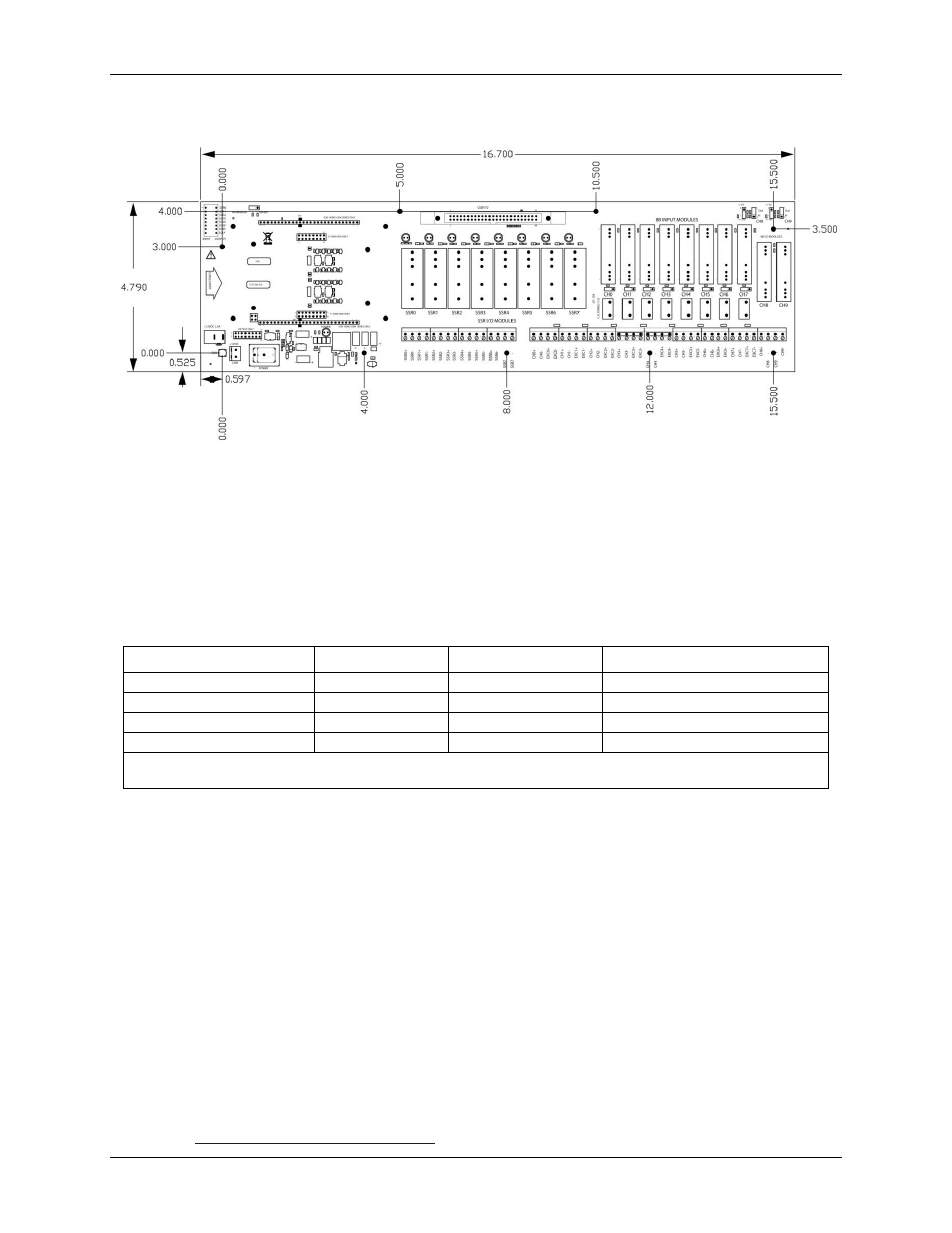
Mechanical drawing
Figure 14. SCC-8-8-2 baseboard mechanical dimensions
Digital output logic control
The behavior of a digital output module is determined by the configuration of SW2, invert logic jumper W1,
and the output logic state set on the OEM DAQ board.
The table below defines how a digital output module behave according to the configuration of the digital output
logic state, the position of
SW2
switches, and the setting of invert logic control jumper
W1
.
Logic table
Digital Output Logic State
SW2 Position
W1 Position
Digital Output Module
Logic 0
Output
Invert
Off
Logic 1
Output
Invert
On
Logic 0
Output
Non-Invert
On *
Logic 1
Output
Non-Invert
Off
* With this configuration, the SSR modules will turn On if the DAQ OEM device loses power. This scenario does not
normally occur because the SCC-8-8-2 is configured by default for inverting logic.
Signal connections
Analog input
Analog input signals CH0 to CH7 are mapped to both the User I/O connector and to 8B analog input locations
CH0 to CH7.
Analog input channels CH8 to CH15 on USB-1608G-OEM Series boards are mapped to the User I/O header
connector only. These signals are not present on the E-1608-OEM board.
Analog output
E-1608-OEM and SC-1608X-2AO-USB channels AOUT0 and AOUT1 are mapped to 8B module locations
CH8 and CH9 and to the header connector.
Locations CH8 and CH9 are wired for output by default.
Use jumpers J29/32 to convert the CH8/CH9 module location to input.
Use jumpers J30/32 to scale the analog output voltage from the default ±10 V to ±5 V.
8B analog I/O module control jumpers
on page 19 for information about the settings for each jumper.