User i/o connector (j35) – Measurement Computing SC-1608 Series User Manual
Page 30
SC-1608 Series User's Guide
Specifications
30
User I/O connector (J35)
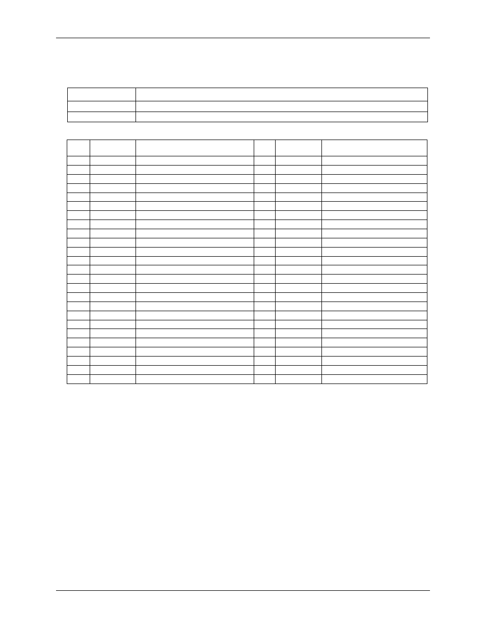
Table 10. 50-pin header connector specifications
Parameter
Specification
Connector type
50-pin header
Pin spacing
0.1 inch
Table 11. User I/O connector J35 pinout
Pin
Signal
name
Pin description
Pin
Signal
name
Pin description
1
CH0
Analog input 0 (single-ended)
2
CH1
Analog input 1 (single-ended)
3
CH2
Analog input 2 (single-ended)
4
CH3
Analog input 3 (single-ended)
5
GND
Ground
6
GND
Ground
7
CH4
Analog input 4 (single-ended)
8
CH5
Analog input 5 (single-ended)
9
CH6
Analog input 6 (single-ended)
10
CH7
Analog input 7 (single-ended)
11
GND
Ground
12
GND
Ground
13
CH8
Analog input 8 (single-ended)
14
CH9
Analog input 9 (single-ended)
15
CH10
Analog input 10 (single-ended)
16
CH11
Analog input 11 (single-ended)
17
GND
Ground
18
GND
Ground
19
CH12
Analog input 12 (single-ended)
20
CH13
Analog input 13 (single-ended)
21
CH14
Analog input 14 (single-ended)
22
CH15
Analog input 15 (single-ended)
23
GND
Ground
24
GND
Ground
25
AOUT0
Analog output 0
26
GND
Ground
27
AOUT1
Analog output 1
28
GND
Ground
29
+VO
+5 V output
30
GND
Ground
31
GND
Ground
32
GND
Ground
33
DIO0
DIO bit 0
34
DIO1
DIO bit 1
35
DIO2
DIO bit 2
36
DIO3
DIO bit 3
37
DIO4
DIO bit 4
38
DIO5
DIO bit 5
39
DIO6
DIO bit 6
40
DIO7
DIO bit 7
41
AICKI
AI clock input
42
AICKO
AI clock output
43
AOCKI
AO clock input
44
AOCKO
AO clock output
45
TRIG
Trigger Input
46
GND
Ground
47
CTR0
Counter 0 Input
48
CTR1
Counter 1 input
49
TMR
Timer output
50
GND
Ground
Note 13:
Analog input signals CH8 to CH15 have no function when the SCC-8-8-2 is connected to the
E-1608-OEM.