E-1608-oem connectors (j3/j4) – Measurement Computing SC-1608 Series User Manual
Page 32
SC-1608 Series User's Guide
Specifications
32
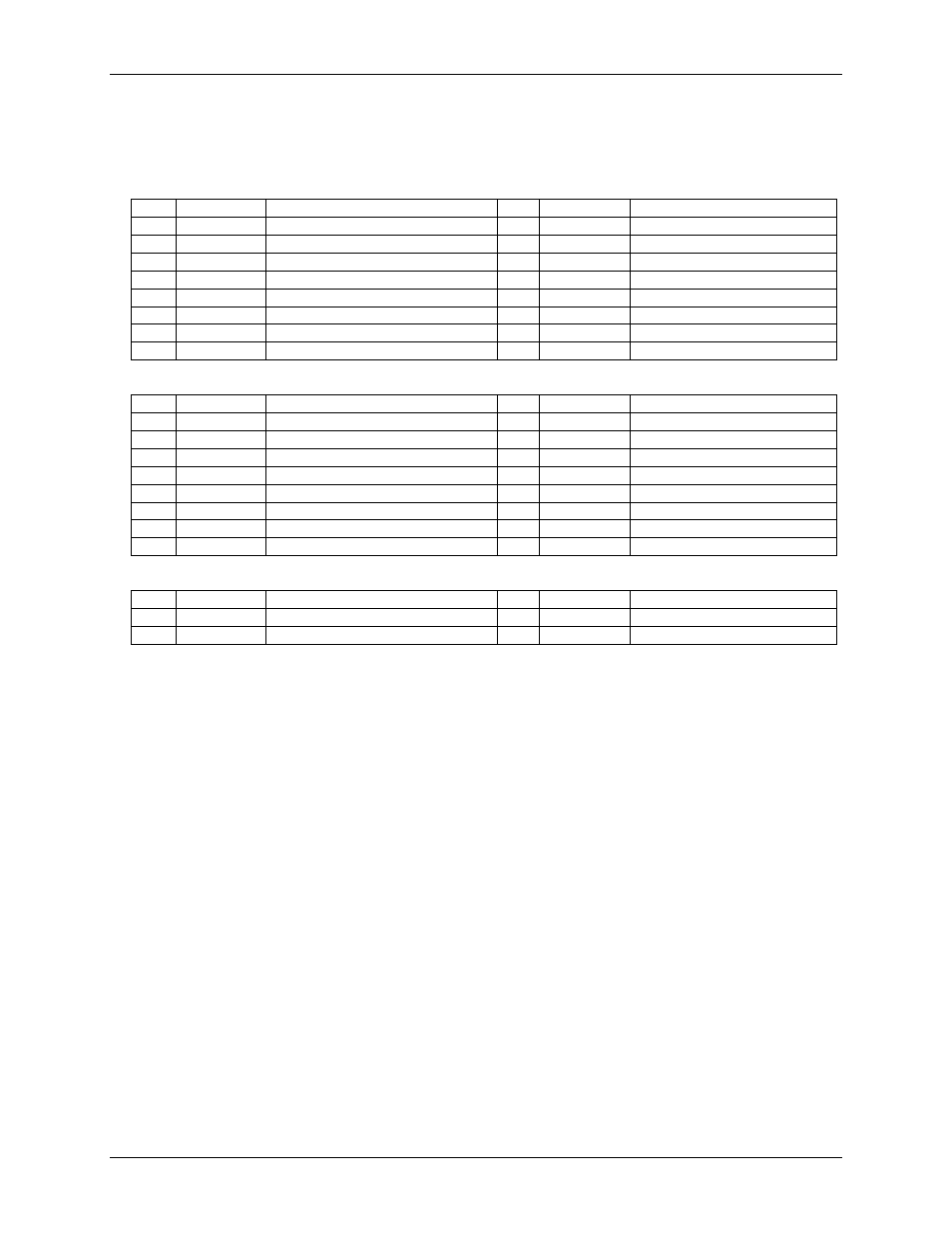
E-1608-OEM connectors (J3/J4)
Use these connectors to mate with an E-1608-OEM board.
Table 13. J3 connector pinout
Pin
Signal name
Pin description
Pin
Signal name
Pin description
1
CH0
Analog input 0 (single-ended)
2
CH1
Analog input 1 (single-ended)
3
GND
Ground
4
CH2
Analog input 2 (single-ended)
5
CH3
Analog input 3 (single-ended)
6
GND
Ground
7
CH4
Analog input 4 (single-ended)
8
CH5
Analog input 5 (single-ended)
9
GND
Ground
10
CH6
Analog input 6 (single-ended)
11
CH7
Analog input 7 (single-ended)
12
GND
Ground
13
AOUT0
Analog output 0
14
GND
Ground
15
AOUT1
Analog output 1
16
GND
Ground
Table 14. J4 connector pinout
Pin
Signal name
Pin description
Pin
Signal name
Pin description
1
DIO0
DIO bit 0
2
DIO1
DIO bit 1
3
DIO2
DIO bit 2
4
DIO3
DIO bit 3
5
DIO4
DIO bit 4
6
DIO5
DIO bit 5
7
DIO6
DIO bit 6
8
DIO7
DIO bit 7
9
GND
Ground
10
+VO
+5 V output
11
GND
Ground
12
AICKO
AI clock output
13
AICKI
AI clock input
14
CTR0
Counter 0
15
TRIG
Trigger input
16
GND
Ground
Table 15. J37 connector pinout
Pin
Signal name
Pin description
Pin
Signal name
Pin description
1
+5V
5V power output
2
GND
Ground
3
NC
Do not connect
4
NC
Do not connect
Note 15:
J37 is used to power the E-1608-OEM. Do not attempt to use this connector for any other purpose.