8b analog input module mounting locations, Cjc enable jumpers, 8b analog i/o module mounting locations – Measurement Computing SC-1608 Series User Manual
Page 18: R1 to r8 resistor locations
SC-1608 Series User's Guide
Functional Details
18
8B analog input module mounting locations
You can install up to eight 8B analog input modules into mounting locations
CH0
to
CH7
.
When using a
product without analog output capability, such as the SC-1608X-USB or SC-1608-USB, you can install a
voltage input module into locations CH8 or CH9, and convert the location to input using an onboard jumper.
Refer to
8B analog I/O module control jumpers
on page 19 for more information about how to use the I/O
module jumpers.
CJC Enable jumpers
Use the CJC Enable jumpers
J21
to
J28
to enable cold-junction compensation for each 8B thermocouple input
module installed in 8B input module locations
CH0
to
CH7
. Configure the jumper directly below the location
where the thermocouple module is installed.
The following table lists the configuration options for CJC Enable jumpers J21 to J28.
CJC Enable Jumpers J21-J28 configuration
J21-J28 Jumper Position
Function
1-2
CJC enabled
2-3
CJC disabled (default)
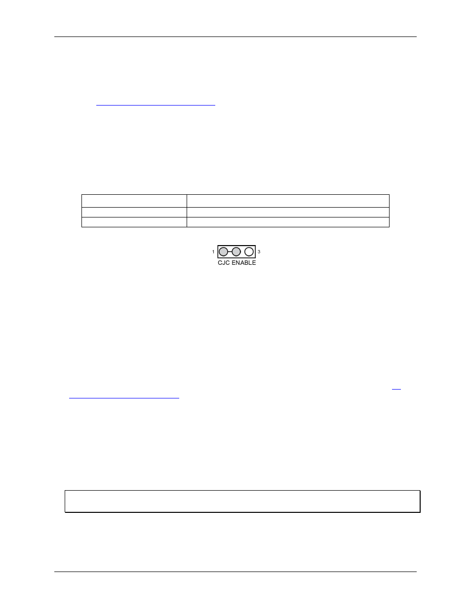
Figure 8 shows a typical jumper configured to enable CJC.
Figure 8. CJC jumper configured to enable CJC
If you are not using thermocouple input modules, make sure that jumpers J21 to J28 are disabled (position 2-3).
8B analog I/O module mounting locations
8B I/O module locations
CH8
and
CH9
are wired for output. When using a product without analog output
capability, such as the SC-1608X-USB or SC-1608-USB, you can install a voltage input module in these
locations. Voltage input modules installed in CH8 and CH9 must be 2-wire types that don't require excitation
terminals. When using the SC-1608-2AO-ENET or SC-1608X-2AO-USB, you must install a voltage or current
output module.
Each I/O module location has an associated pair of jumpers that let you either convert the location to input, or
read back an output voltage at the header connector, depending on the type of module installed. You can also
scale the default analog output voltage to match the range of an installed 8B output module. Refer to the
analog I/O module control jumpers
section on page 19 for details about how to use the jumpers.
R1 to R8 resistor locations
You can install plug-in shunt resistors at locations R1 to R8 to monitor a 4-20 mA current loop, or to measure
current using 8B analog voltage input modules.
Complete the following steps to monitor a 4-20 mA current loop or to measure current:
1. Turn the baseboard power switch
SW1
OFF.
2. Plug the shunt resistor into the plug-in location for the applicable voltage input module. DO NOT solder
the resistor in place.
Shunt resistors can only be used with 8B voltage input modules
Shunt resistors must be removed when using other types of input modules, including current input modules.
Voltage input modules used to monitor a 4-20 mA loop often use a 250 Ω precision resistor to develop a 1 VDC
to 5 VDC voltage drop.