Measurement Computing SC-1608 Series User Manual
Page 20
SC-1608 Series User's Guide
Functional Details
20
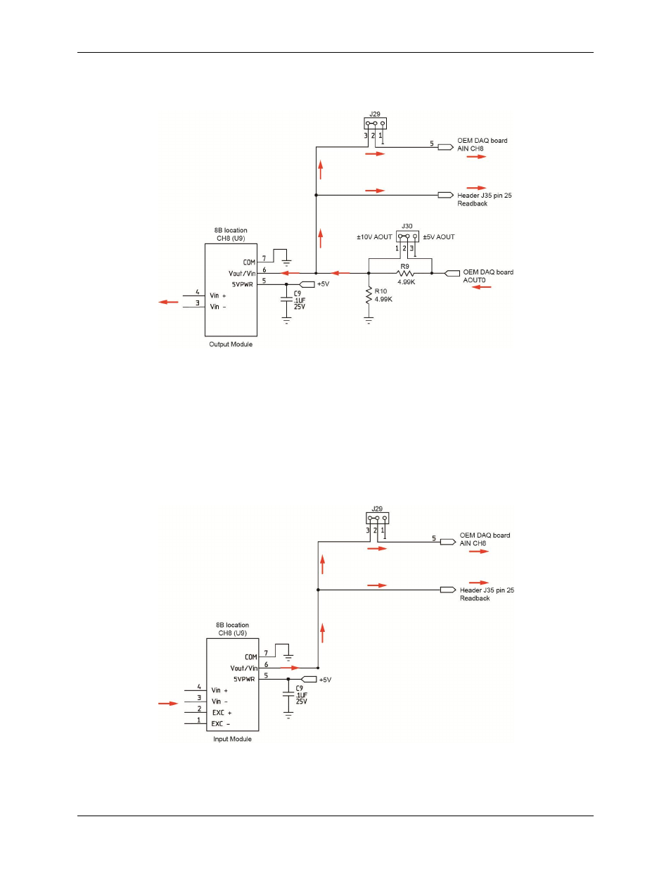
Figure 10 illustrates the connection flow when an output module is installed in module location CH8, and
jumper J29 is set for position 2-3.
Figure 10. J29 set for position 2-3 with an output module installed in CH8 (U9)
In this scenario, the value of the voltage output from OEM DAQ board channel AOUT0 can be read from OEM
DAQ analog input channel CH8 at J35 pin 13 when using the SC-1608X-2AO-USB. When using the SC-
1608X-2AO-USB, the OEM DAQ AOUT0 voltage can be read with a meter or other DAQ board at J35 pin 25
(AOUT0) .
When set to position 1-2 (not shown in the diagram), the same voltage readback functionality is available using
J35 pin 25 and non-isolated analog input CH8 (pin 13). The signal is non-isolated in this configuration, since
the AOUT0 signal is no longer connected to AIN CH8.
Figure 11 illustrates the connection flow when an input module is installed in module location CH8, and jumper
J29 is set for position 2-3.
Figure 11. J29 set for position 2-3 with an input module installed in CH8 (U9)
In this scenario, the value of the input module's output voltage can be read from J35 header pin 13 when using
the SC-1608X-2AO-USB. The output value can also be read from header pin 25 with a meter or other DAQ
board when using the SC-1608-2AO-ENET or SC-1608X-2AO-USB.