Functional details, Scc-8-8-2 baseboard components, External power connectors – Measurement Computing SC-1608 Series User Manual
Page 14: Chapter 3
14
Chapter 3
Functional Details
This chapter discusses the functional details of the SCC-8-8-2 baseboard. For functional details of the OEM
DAQ board, refer to the hardware manual specific to the SC-1608 Series;
USB-1608GX-2AO-OE
USB-1608GX-OE
USB-1608G-OE
E-1608-OEM:
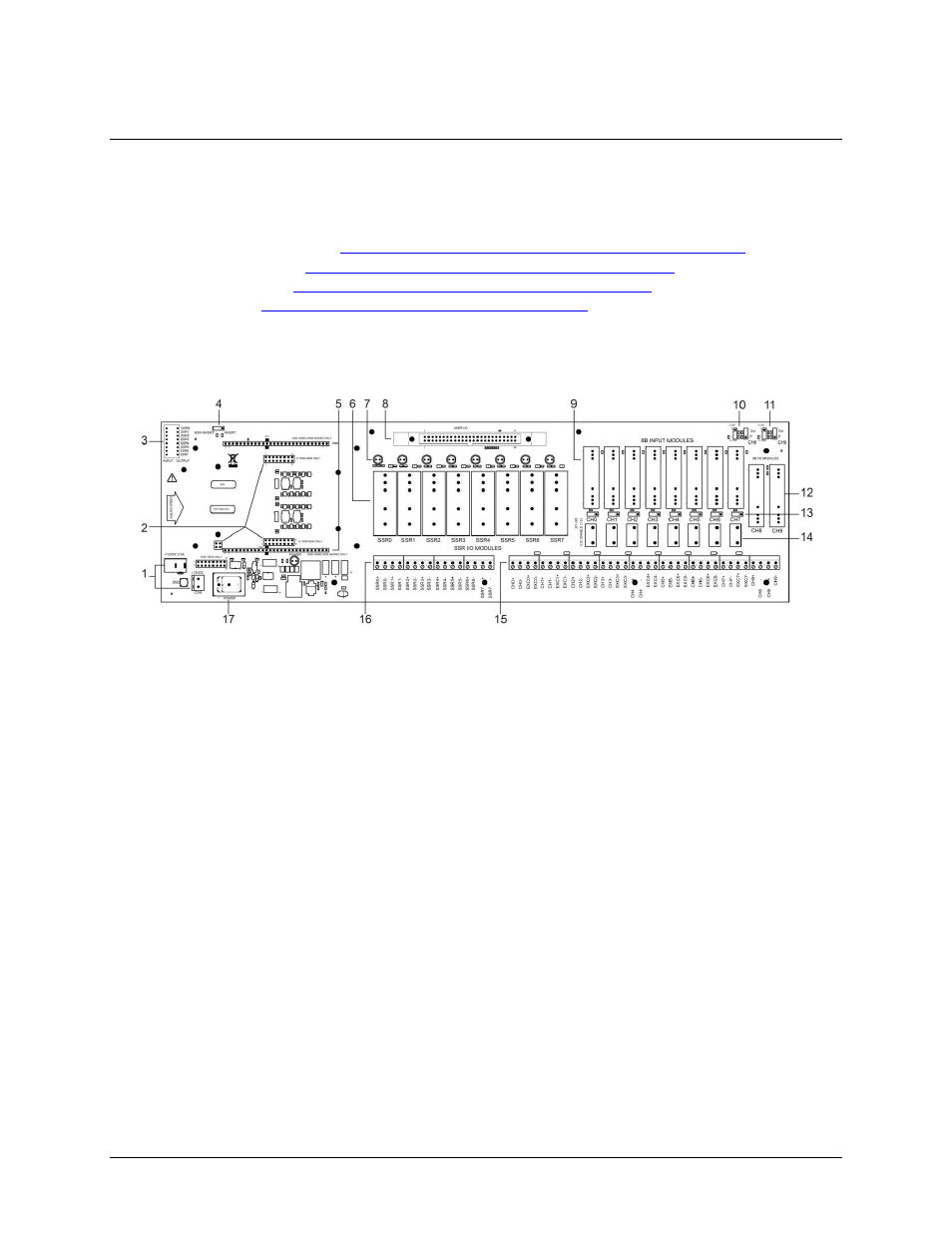
SCC-8-8-2 baseboard components
The location of each component on the baseboard is shown in Figure 4.
1
External power connectors J1 and J2
10
8B I/O module control jumpers J29 and J30 (for CH8)
J29: AOUT0 readback or convert to input module location
J30: AOUT0 voltage divider
2
E-1608-OEM connectors J3, J4, and J37
11
8B I/O module control jumpers J31 and J32 (for CH9)
J31: AOUT1 readback or convert to input module location
J32: AOUT1 voltage divider
3
8-position DIP switch for SSR module direction
12
8B I/O module mounting locations CH8 and CH9
4
Non-invert/Invert logic control jumper W1
13
CJC Enable jumpers J21 to J28
5
USB-1608G-OEM Series connectors J5to J6
14
R1 - R8 resistor locations
6
SSR I/O module mounting locations SSR0 to SSR7
15
8B module screw terminals
7
SSR I/O module status LEDs (8)
16
SSR I/O module screw terminals
8
User I/O header connector J35
17
Power switch SW1
9
8B input module mounting locations CH0 to CH7
Figure 4. SCC-8-8-2 baseboard components
External power connectors
External power can be connected to either power connector
J1
(barrel connector) or
J2
(terminal block). Do not
attempt to apply power to both power connectors simultaneously.
Connector
J1
connects to the +12 VDC external power supply included in the SCC-8-8-2 shipment.
Connector
J2
connects to a user-supplied +12 VDC power supply.
Figure 5 shows a schematic for external power connectors J1 and J2.