8b analog i/o module screw terminals – Measurement Computing SC-1608 Series User Manual
Page 22
SC-1608 Series User's Guide
Functional Details
22
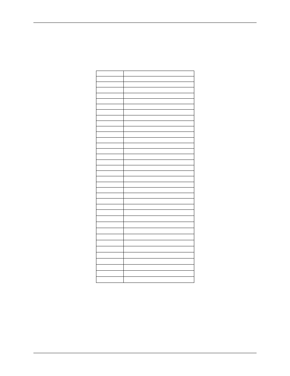
8B analog I/O module screw terminals
Connect 8B analog input module signals to screw terminals labeled
CH0+
/
CH0
–
to
CH7+
/
CH7
–
and the
associated excitation terminals
EXCx+
/
EXCx
–
. Connect 8B analog output module signals to
CH8+
/
CH9+
and
CH8
–
/
CH9
–
. Use 16 AWG to 30 AWG wire when connecting signals.
8B module screw terminals
Signal name
Pin description
CH0+
8B input module CH0+
CH0
–
8B input module CH0
–
EXC0+
8B input module excitation CH0+
EXC0
–
8B input module excitation CH0
–
CH1+
8B input module CH1+
CH1
–
8B input module CH1
–
EXC1+
8B input module excitation CH1+
EXC1
–
8B input module excitation CH1
–
CH2+
8B input module CH2+
CH2
–
8B input module CH2
–
EXC2+
8B input module excitation CH2+
EXC2
–
8B input module excitation CH2
–
CH3+
8B input module CH3+
CH3
–
8B input module CH3
–
EXC3+
8B input module excitation CH3+
EXC3
–
8B input module excitation CH3
–
CH4+
8B input module CH4+
CH4
–
8B input module CH4
–
EXC4+
8B input module excitation CH4+
EXC4
–
8B input module excitation CH4
–
CH5+
8B input module CH5+
CH5
–
8B input module CH5
–
EXC5+
8B input module excitation CH5+
EXC5
–
8B input module excitation CH5
–
CH6+
8B input module CH6+
CH6–
8B input module CH6–
EXC6+
8B input module excitation CH6+
EXC6–
8B input module excitation CH6–
CH7+
8B input module CH7+
CH7–
8B input module CH7–
EXC7+
8B input module excitation CH7+
EXC7–
8B input module excitation CH7–
CH8+
8B I/O module CH8+
CH8–
8B I/O module CH8–
CH9+
8B I/O module CH9+
CH9–
8B I/O module CH9–
Note that excitation terminals are provided only for analog input modules installed in
CH0
to
CH7
, and are not
provided for locations
CH8
or
CH9
, even if a voltage input module is installed.