Ssr module i/o control, Digital input/output – Measurement Computing SC-1608 Series User Manual
Page 26
SC-1608 Series User's Guide
Specifications
26
Note 3:
The voltage divider jumper options let you scale the OEM ±10V AOUTx to a ±5V output. To make
this change, place either of the J30 (CH8) and J32 (CH9) jumpers in the 2-3 position.
SSR module I/O control
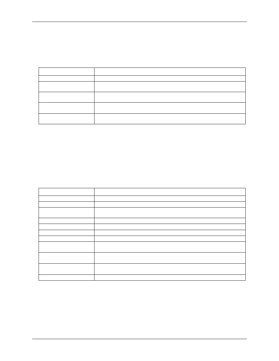
Table 3. SSR module specifications
Parameter
Specification
Number of I/O control logic
8
SSR default configuration
(Note 4)
OUTPUT type (SW2 default)
Configuration
Each module location (SSR0–SSR7) is individually configurable as INPUT or OUTPUT
using switch SW2.
Logic inversion control
(Note 5)
Configurable for inverting or non-inverting logic with jumper W1; set by default to
INVERT.
LED
Each module location (SSR0-SSR7) has a dedicated LED for indicating the module
status.
Note 4:
Set the SW2 DIP switch to INPUT for use with SSR input modules such as the Grayhill 70IDC5.
The OEM DAQ board should be configured for digital input mode.
Set the SW2 DIP switch to OUTPUT for use with SSR output modules such as the Grayhill
70ODC5. The OEM DAQ board should be configured for digital output mode.
Note 5:
The inverting logic feature is applied to SSR digital output modules only. The setting of jumper W1
has no effect on SSR digital input modules.
Digital input/output
Table 4. Digital input/output specifications
Parameter
Specification
Digital type
5V TTL
Number of I/O
8
Configuration
Bidirectional: each bit is individually configurable as digital input or digital output using
DIP switch SW2 (Note 6).
Connector location
J35
Input high voltage threshold
2.0 V min
Input high voltage limit
5.5 V absolute max
Input low voltage threshold
0.8 V max
Input low voltage limit
–0.5 V absolute min
0 V recommended min
Output high voltage
4.4 V min (IOH = –50 µA)
3.76 V min (IOH = –24 mA)
Output low voltage
0.1 V max (IOL = 50 µA)
0.44 V max (IOL = 24 mA)
Power On default state
Digital output, +5V logic level
Note 6:
Take care to avoid creating a digital I/O logic contention state between the DAQ board DIO and the
SCC-8-8-2 DIO.