Description of the broadband digitiser – Guralp Systems CMG-DM24 User Manual
Page 55
Operator’s Guide DM-24 Digitiser
Issue G January 2003
53
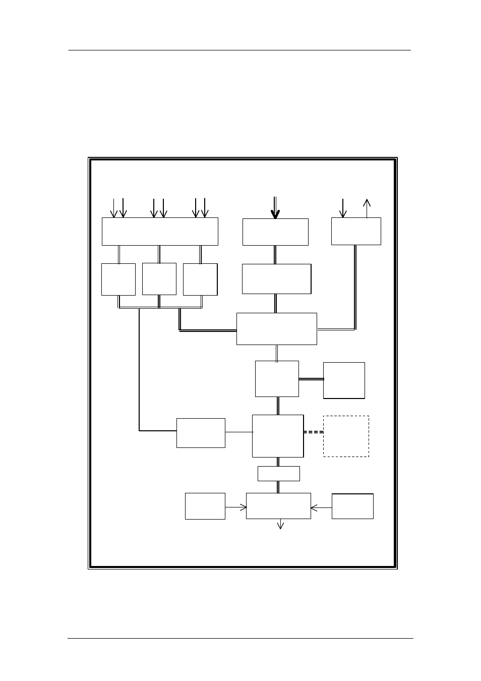
8. DESCRIPTION OF THE BROADBAND DIGITISER
The DM24 system design block diagram is given below. Each section of the block
diagram represents a separate printed circuit board. Depending on the CMG-DM24
configuration, the printed circuit boards are stacked up either as circular PCB, square
circuit boards or long and slim PCBs for the borehole digitiser.
The high resolution digitiser utilises the Crystal Semiconductor CS5321/2 chipset and
Motorola 56002 DSP. The CS5321/2 provides data at 2,000 samples per second,
56002
DSP
RAM
Field Programmable
Gate Array
16 way
multiplexor
16 bit ADC
16 analogue
inputs
Pre-amplifier
Module
ADC1
24 bit
ADC2
24 bit
ADC3
24 bit
Differential analogue inputs
Z N/S E/W
Digital I/O
16 digital
I/O channels
H8
Micro-
processor
Precision
Clock
Buffer
Opto-isolated
UARTS
GPS
Power
supply
Data
Optional
16 Mb
Si file