Guralp Systems CMG-DM24 User Manual
Page 47
Operator’s Guide DM-24 Digitiser
Issue G January 2003
45
The offset and drift figures are the total accumulated error measurements during the
previous minute in time-base units (nominally 0.5
µ
sec). To convert the figures to time,
divide by 120 (60 * 2) to give micro-seconds. In a stable temperature environment the
system should soon settle down showing an offset error of only a few thousand (average
error < 100
µ
sec) and a drift rate under 100 counts (< 1 in 10
-6
).
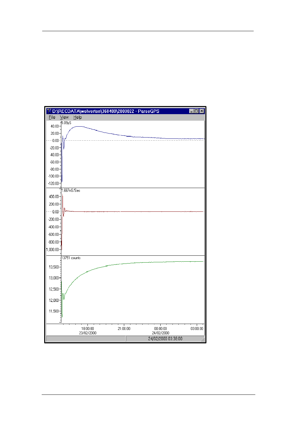
The screen shot below shows, from the top graph down, the offset, drift and pwm of a
digitiser internal clock tracking and homing-in on a GPS clock pulse over
approximately a twelve hour period.
The above graphical image was printed from a Guralp plot module to demonstrate the
effectivenes of digitiser clock sychronisation and subsequently time stamped data.
Offset or phase
error between
digitiser internal
1Hz and GPS
1pps.Closes in to
less than 5
µ
s
Drift or frequency
error between
digitiser internal
clock and GPS
PWM – Pulse Width
Modulation control
signal applied to a
DtoA to control
internal clock/GPS
error