Adding a digitiser module onto a broadband sensor – Guralp Systems CMG-DM24 User Manual
Page 51
Operator’s Guide DM-24 Digitiser
Issue G January 2003
49
6. ADDING A DIGITISER MODULE
ONTO A BROADBAND SENSOR
The CMG-DM24 module is connected onto a Guralp sensor by a ribbon cable. A
ribbon is used as the cable length is only 150mm. The input stage of the CMG-DM24
module is single ended to save power and component count (see pin connections in the
Pin-out section).
In order to fit a digitiser module onto the top of a standard Guralp analogue output
instrument it is necessary to follow the following procedure.
It is essential that all the sensors are in a locked state (if applicable)
throughout this procedure.
1.
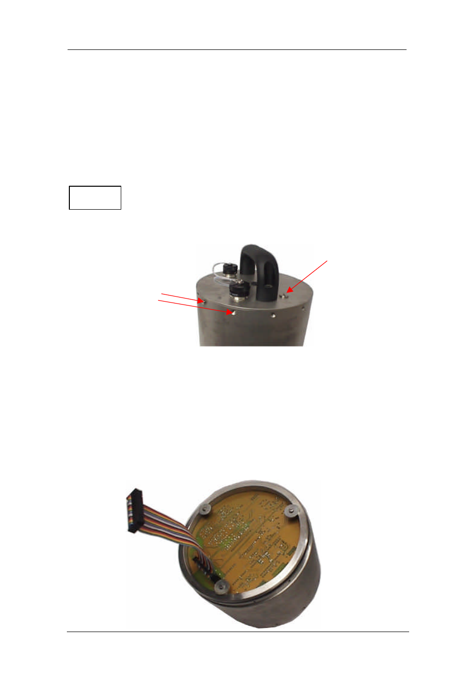
Unscrew 12 sets (can be 6 sets) of M3 x 6 cap head screws retaining the top lid of
the sensor.
2.
Remove the pressure relief valve before gently pulling the top lid off the sensor
pressure housing tube.
3.
Under the lid there is a short ribbon cable assembly. Unplug the cable assembly
from the top circuit board in the sensor.
4.
Remove the air pressure relief screw from the digitiser.
5.
Use the ribbon cabling provided with the digitiser, to connect the digitiser module
onto the broadband sensor.
NOTE
Remove screws
retaining lid
Pressure relief
screw
Bottom view of
digitiser module with
ribbon cable provided