Guralp Systems CMG-DM24 User Manual
Page 46
Operator’s Guide DM-24 Digitiser
Issue G January 2003
44
control process the system reports the measured errors and the control signal applied, as
a ‘pwm’ value - Pulse Width Modulation - digital to analogue conversion.
During the initial ‘coarse’ adjustment only the coarse voltage control is used and no
‘drift’ calculation is made (drift is initially shown as ‘0’). If the system is operating in a
similar environment to that when the system was last powered (i.e. same temperature)
the saved control parameters will be appropriate and the system should rapidly switch to
the ‘fine’ control mode.
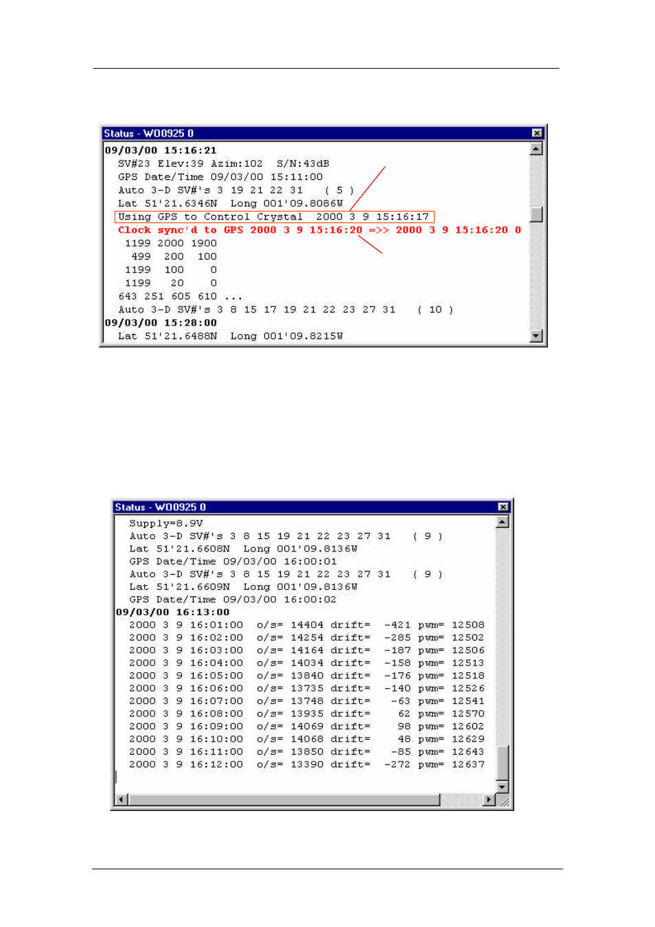
The system reports its control status and parameters each minute as shown below:
Synchronisation control
parameters.(zero ‘drift’ in
the first instance during
coarse adjustment. ‘pwm’ is
a saved parameter)
Internal clock synchronised to GPS. Notice the date
and time are repeated.
The first is the internal clock, the second is the GPS
time the clock will change to, if there is a difference.
Synchronisation
process commenced