Guralp Systems CMG-DM24 User Manual
Page 24
Operator’s Guide DM-24 Digitiser
Issue G January 2003
22
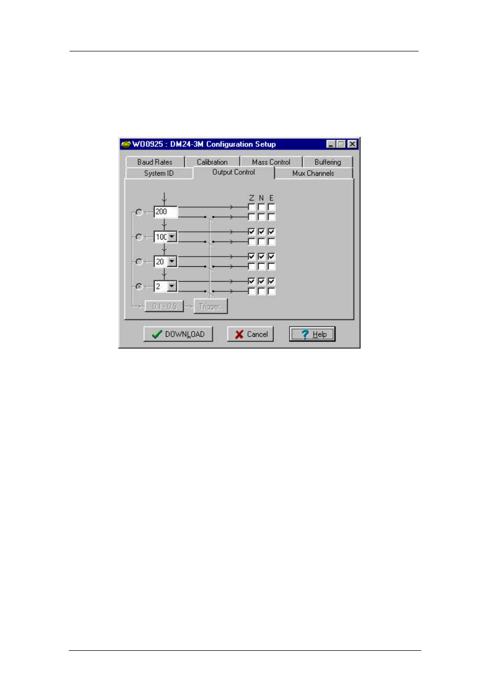
DIGITISER OUTPUT CONTROL PROGRAMMING
The screen shot below shows the Output Control window for a CMG-DM24-S3
standalone digitiser. The digitiser module set-up will appear the same. The CMG-
DM24-S6 will display an extra 3 columns (Z, N and E) on the right –hand side,
corresponding to the extra three channels available on that model.
Sampling rate: The output of the digitiser’s analogue-to-digital converters (ADC) is
data sampled at 2000 Hz. These data are filtered and reduced to lower rates
using a digital signal processor (DSP). The DSP has 4 cascaded
filter/decimation stages each of which can be programmed for decimation
factors of 2, 4, 5, 8 or 10. The output of each stage is called a “tap”. The first
filter stage, tap 0, is preset to reduce the data by a factor of 10 to 200
samples/second, but each of the subsequent stages may be configured for a
different decimation factor.
The four windows on the left of the Output Control screen (shown above)
allow you to select the sampling rates for three of the four digitiser taps. The
upper window corresponds to tap 0 and has a fixed sampling rate of 200 Hz.
Each of the other taps may have a sampling rate lower than its predecessor
above, if the rate can be achieved by decimation by 2, 4, 5, 8 or 10. Clicking on
the window shows a list of the rates that are permitted, given the sampling rate
in the window above it.
If some of the outputs are not required then leave the buttons ‘unticked’ to save
communications capacity.
Stream selection: The CMG-DM24-S3 has three channels or streams. These are
depicted by the three columns of small windows labelled Z, N and E in the
Output Control window shown above.