Sump float installation, Figure 8 – Gasboy Blackmer GDP User Manual
Page 17
MDE-4096C Blackmer® Global Dispenser Pump Operation, Maintenance and Kit Installation Manual · April 2008
Page 17
Maintenance
Sump Float Installation
To install the sump float, proceed as follows:
1
Install the sump return float assembly (2) or sump overflow float assembly (23), holding the
mount to the casing with one finger and inserting the two screws (24) with the other hand.
Ensure that the rubber washer has not fallen out and is properly seated in the recess of the float
assembly mount (see
).
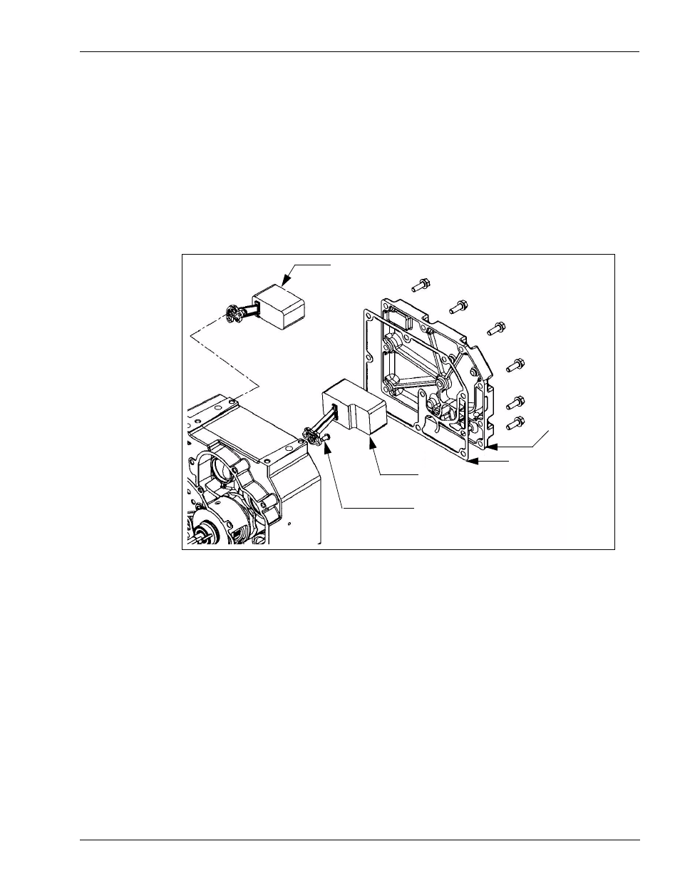
Figure 8: Sump Float Assembly
Sump Overflow Float Assy. Option (23)
Sump Return Float Assy. (2)
Mounting Screws (24)
Gasket (3)
Sump Cover (4)
Sump Cover Screws (5)
2
Tighten the screws (24) to a torque of 18 in. lbs (2 Nm).
3
Check float mechanism. It should operate freely. At full down position, the sump return float
valve should center and seal against the rubber seal surface. The sump overflow float assembly
should seat when the float is fully elevated.
4
Install the sump cover gasket (3). Correctly position the gasket onto all sealing surfaces.
5
Lower the sump cover (4) gently into place over the gasket with the pins aligned, while
ensuring that you do not move the gasket.
6
Install and tighten the center-most sum cover screw (5) to 200 in. lbs (23 Nm).
7
Install the remaining sump cover screws and tighten to 200 in. lbs (23 Nm), alternating in a
cross pattern.