System installation, A. st300-s/sm, vtr/ddr c, B. st420 shotbox – DNF Controls 2034CL-N User Manual
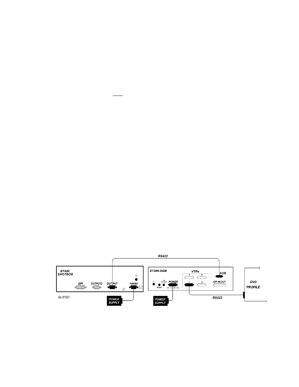
Page 6: Connection diagram
6 2034CL-N, 300 Clip Instant Access System, Profile, NATIVE Protocol
3.
SYSTEM INSTALLATION
a.
ST300-S/SM, VTR/DDR C
ONTROLLER
1)
Plug one end of a 9-conductor, RS422 serial cable into the VTR 1 (2, 3 or 4)
connector on the rear of the ST300. Plug the other end of the cable into the 9-
pin REMOTE connector on the Video Server.
2)
Connect the +5, +12, -12 VDC POWER SUPPLY into the POWER connector
on the rear of the ST300. Plug the Power Supply into an outlet, 90 VAC to 240
VAC.
Do NOT Hotplug!!!
3)
Check SETUP MENU prior to using the ST300 to confirm proper Record mode
and other User settable modes. See CONFIGURING THE PROFILE FOR
NATIVE MODE, Section 20.a.
b. ST420
SHOTBOX
1)
Plug one end of a 9-conductor, RS422 serial cable into the OUTPUT connector
on the rear of the SHOTBOX. Plug the other end of the cable into the “AUX”
connector on the ST300.
2)
Connect the +5,VDC POWER SUPPLY into the POWER connector on the rear
of the SHOTBOX. Plug the Power Supply into a wall outlet, 90 VAC - 240
VAC.
Installation is complete.
CONNECTION DIAGRAM