Media converter, Location of can termination jumper, Figure 46: media converter – Daktronics AF-3197-89-RGB User Manual
Page 56
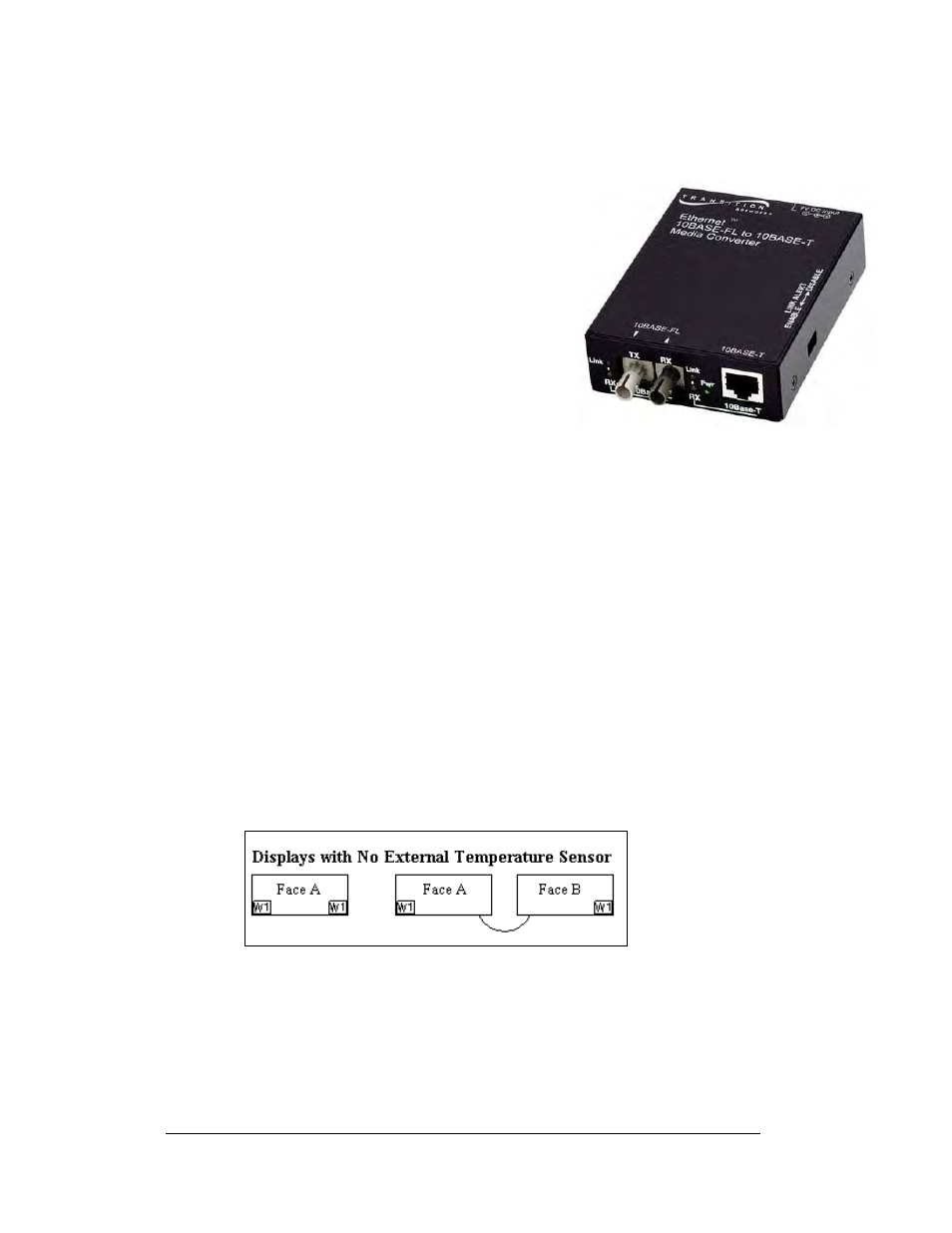
Media Converter
If a media converter was included with the display, it is located inside the display
next to the controller board.
Figure 46: Media Converter
1. To replace the media converter, first
disconnect the power and signal connections
(refer to
2. The media converter is attached to a plate
with four screws. Carefully remove them
using a 3/16” nut driver.
3. The media converter is held to the plate by
two screws. Release the two screws that hold
the media converter to the plate.
4. Install the new media converter, replace the
screws, reattach the plate, and reconnect the
power and signal cables.
The fiber media converter has the following input and
output jacks:
1. The fiber transmit and receive jacks are marked by arrows showing their
function. They are labeled “10BASE-FL”. The fiber cable from the indoor
media converter will connect to these jacks.
2. The input/output Ethernet signal to the display controller is routed through
an RJ45 jack, labeled “10BASE-T”.
3. The DC power input from the TB1 on the display controller is connected
into the media converter at a jack labeled “9V DC Input”.
Location of CAN termination jumper
Temperature and light sensors are controlled as part of a CAN network. For the CAN
network to work correctly, the network must be terminated at both ends of the
network. This is true for a single display, or multiple displays. The correct
terminations are completed during the building process. However, if the order or
number of displays is changed on-site, the terminating jumper may need to be
relocated.
In the case of those displays that utilize a temperature sensor, the sensor is internally
terminated. Therefore, only one other termination needs to be made at the output of
the last sign in the network. The most common input location for the temperature
sensor is to the first display in the network.
Figure 47: Displays with No External Temperature Sensor
Maintenance and Troubleshooting
4-12