Venus® 1500 radio client, Venus, 1500 radio client -15 – Daktronics AF-3197-89-RGB User Manual
Page 37: Figure 28: fiber signal connections, Figure 28
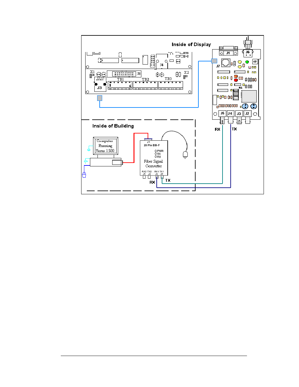
Figure 28: Fiber Signal Connections
Venus
®
1500 Radio Client
Reference Drawings:
System Riser, QC Outdoor Radio, V1500 ................... Drawing A-185359
Schem, Sig Wiring, Internal, W/Q CPCB ..................... Drawing B-177662
A display that is controlled using a radio requires a server radio connected to the
control computer, and a client radio connected to the display using a pre-terminated
cable. The following conditions are required for good radio operation:
1. The radios must be within line-of-site of each other.
2. The total distance between the outdoor radios should not exceed 1500 feet.
3. The antennas for the server and client radio should be in a parallel position
with each other.
Refer to Drawing A-185359 and
for system layout.
Electrical Installation
3-15