Rs422, Rs422 -11, Figure 23: rs422 display layout – Daktronics AF-3197-89-RGB User Manual
Page 33
RS422
Reference Drawings:
System Riser Diagram, RS422 .................................... Drawing A-174135
Schem, Sig Wiring, Internal W/QC PCB ...................... Drawing B-177662
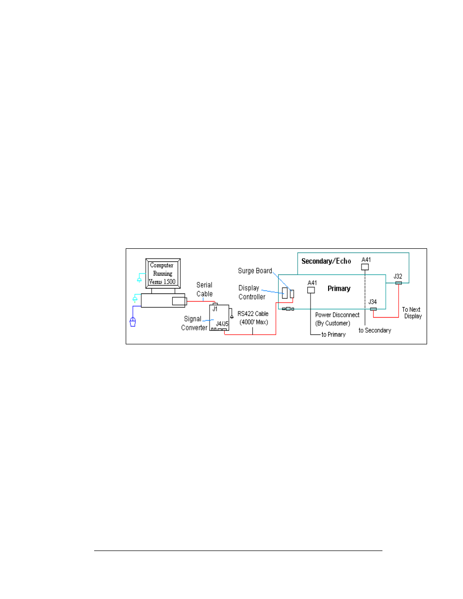
A display that is controlled using RS422 requires the use of signal converter
(0A-1127-0255) at the computer. From the signal converter, cable is run to the surge
board assembly in the display. The cable from the signal converter to the display
must be routed though conduit. Do not run signal and display power through the
same conduit. Refer to
and Drawing A-174135 for system layout.
1. When connecting to the surge card (0P-1146-0031) in the display, terminate
one end at signal converter (J4 or J5) and the other end of the wire to the 6-
position terminal block on the surge board assembly labeled “RS422 IN”
(TB1).
2.
and Drawing B-177662 shows the terminal block wiring. The
terminal block wiring is pinned one-to-one.
3. The computer connects to the signal converter through a DB9 to DB25
serial cable (W-1249).
Figure 23: RS422 Display Layout
Electrical Installation
3-11