Rs422 interconnection, Rs422 interconnection -16, Figure 35: display interconnect cable – Daktronics AF-3197-89-RGB User Manual
Page 41: Figure 36: rs422 interconnection
4. The media converter in the display connects to the controller via an RJ45
cable (W-1506). It also receives power from pins one and four of TB1 on
the controller.
5. The Ethernet connections are shown in
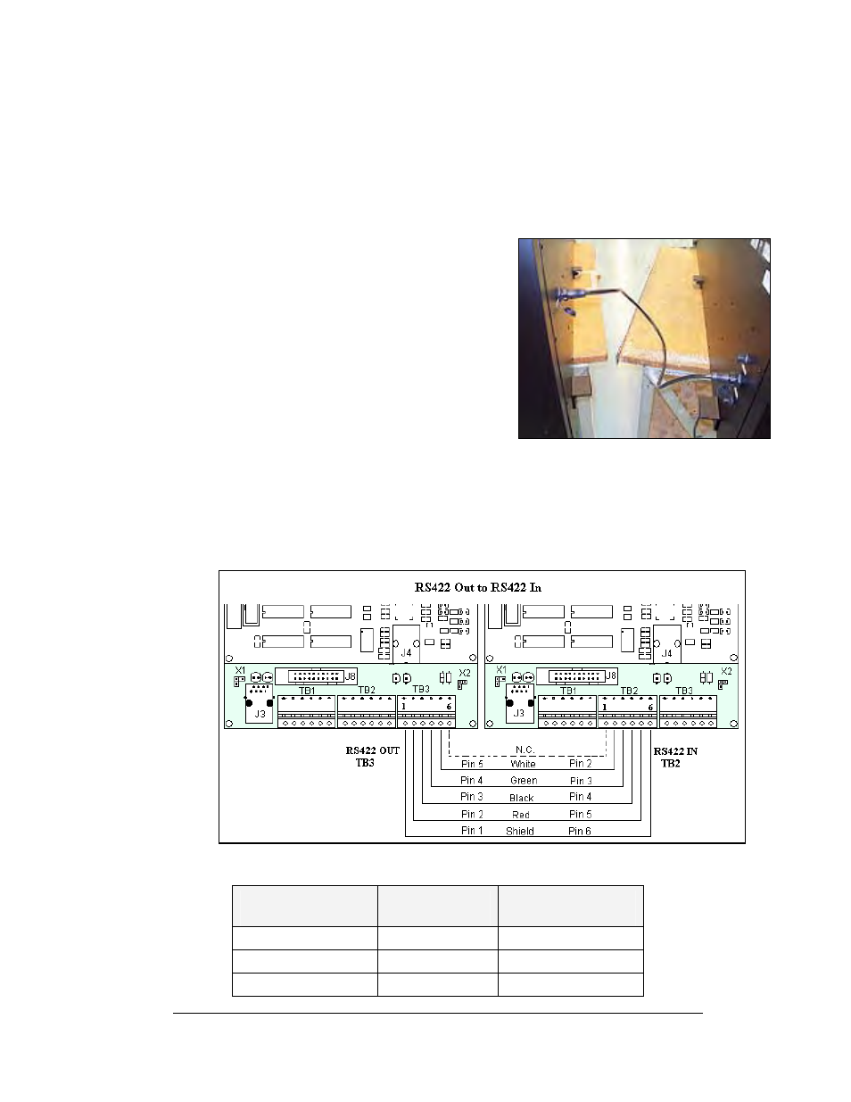
RS422 Interconnection
The quick connect cable is the most common method of terminating signal between
two displays. The interconnect cable goes from
the RS422 OUT on the first display to the RS422
IN on the second display. The 10-position, quick
connect cable comes in either 6 or 10 foot
lengths.
If the displays are not back-to-back, or are too far
apart for the quick connect interconnect cable to
reach, a 4-conductor shielded cable of the correct
length is used. One end will connect at the
“RS422 OUT” 6-position controller board
terminal block (TB3) in the first display, and
terminate on the “RS422 IN” 6-position controller
board terminal block (TB2) on the second display.
Note: If a temperature sensor is also used, a separate cable must also be used to
connect between controllers. Appendix C explains the connections for a
temperature sensor.
RS422 Interconnection
Figure 35: Display Interconnect Cable
Figure 36: RS422 Interconnection
Face A RS422 Out
(TB3)
Field Cabling
Face B RS422 IN
(TB2)
Pin 1 (GND)
Shield
Pin 6 (GND)
Pin 2 (D2OUT-N)
Red
Pin 5 (D1IN-N)
Pin 3 (D2OUT-P)
Black
Pin 4 (D1IN-P)
Electrical Installation
3-19