Service and diagnostics, Line filter, Modules, pixel strips and drivers – Daktronics AF-3197-89-RGB User Manual
Page 48: Service and diagnostics -4, Line filter -4, Modules, pixel strips and drivers -4, 6 service and diagnostics
4.6 Service
and
Diagnostics
Reference Drawings:
Component Layout, AF-3190-**X***-89mm ................ Drawing B-181666
The following sub-sections address servicing of the below display components:
•
Line filter and ground bar
•
Modules, drivers, and power supplies
The sub-sections also address any diagnostic LEDs, fuses, and signal/power
connectors found on the components.
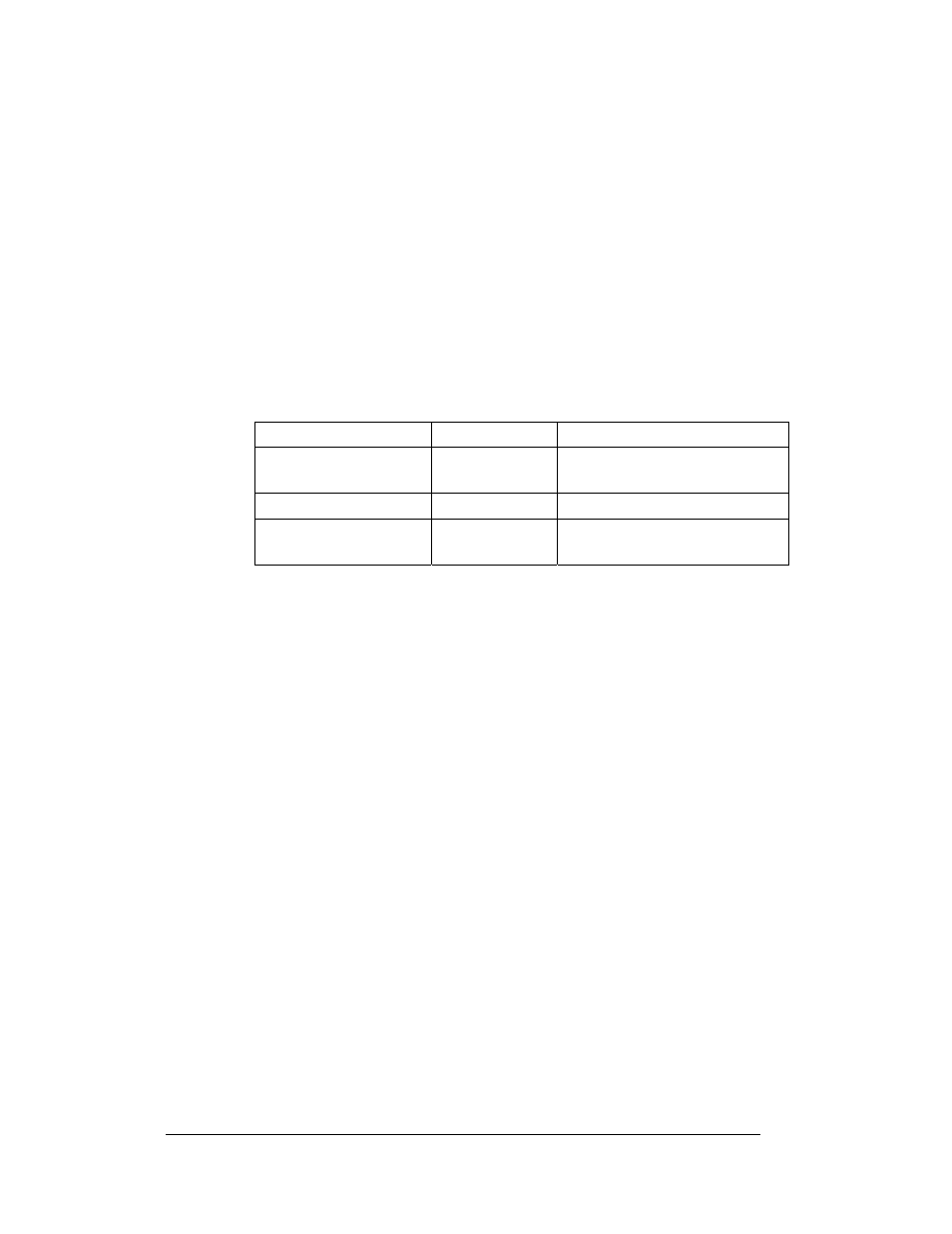
Drawing B-181666 denotes the components as follows:
Line Filter
Reference Drawings:
Z Filter Assy, 2 W/Grnd Bar .................................. Drawing A-158472
Schematic, AF-3197-8-48x32x***-89, RGB .......... Drawing A-184111
You can replace the filter by first removing all connecting wires, and then releasing
the attachment hardware. Refer to Drawing A-158472 for more information. Install
the new filter and refer to Drawing A-184111 for the correct wiring.
Modules, Pixel Strips and Drivers
Reference Drawing:
Driver Assy; AF-3197-8x8-89mm-RGB ....................... Drawing A-183737
Module Panel, AF-3197-8x8-89mm-RGB ................... Drawing A-182812
Driver; Large Pixel-8x8-RGB ....................................... Drawing A-182600
A module consists of louvers, 16 pixel strips per module, and a driver board mounted
to the back. Refer to Section 4.5 to open a display via the modules and access the
pixel strips and driver boards.
A pixel strip is a circuit board with four LED pixel clusters mounted directly on it.
Each pixel strip is removable from the module. To remove a pixel strip from the
module:
Component… Denoted
As…
Location…
Line Filters and Ground
Bar
0A-1259-4003
Left side, behind module AX02
Modules
0A-1259-3126
Over entire face of the display
Power Supplies
0A-1259-4410
Behind the modules; refer to
Drawing B-181666.
1. Open the display as described in Section 4.5.
2. Disconnect the power and signal connector from the strip you wish to
replace. Refer to Drawing B-182812 for more information.
Maintenance and Troubleshooting
4-4