Daktronics AF-3197-89-RGB User Manual
Page 52
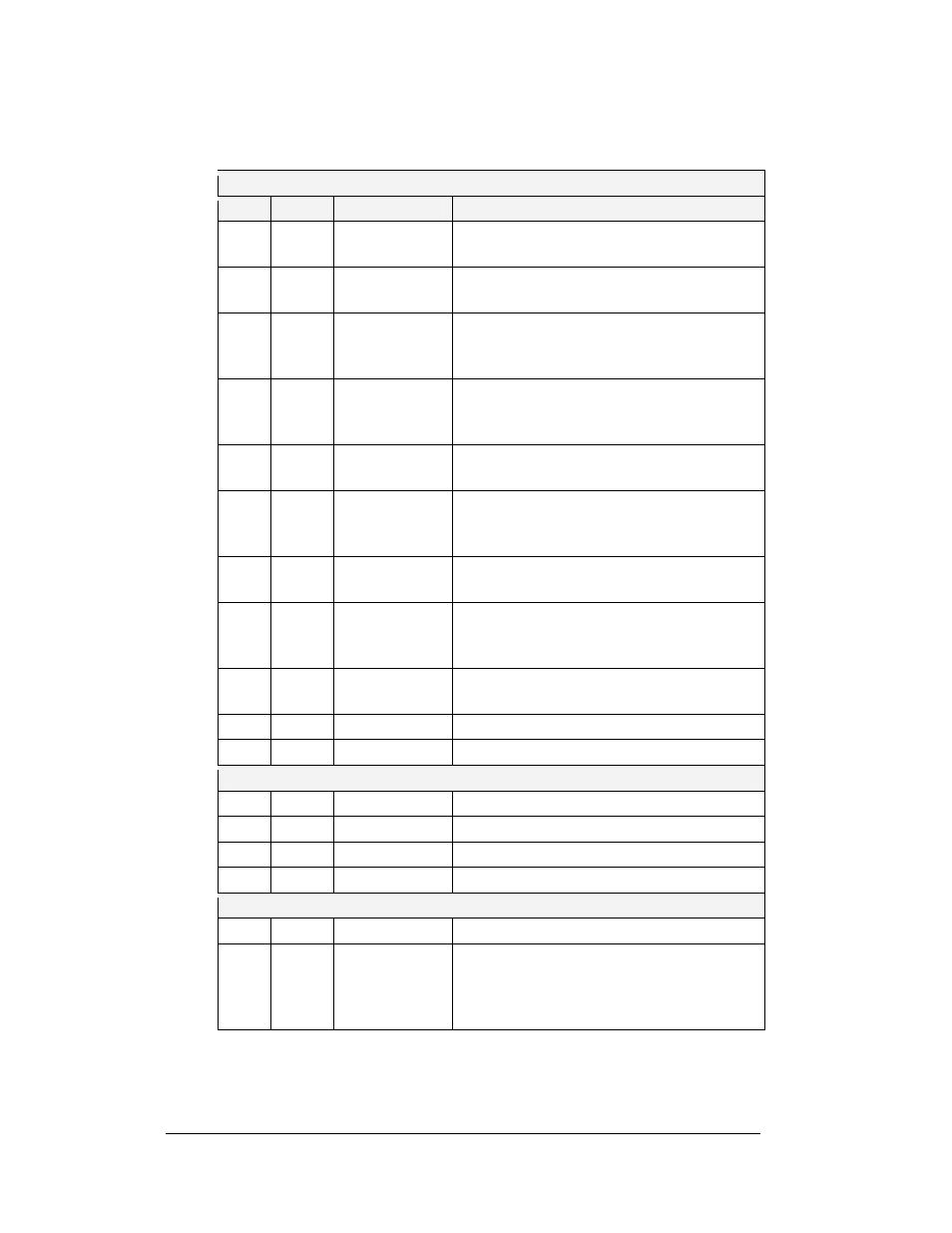
Four diagnostic LEDs are located on the controller; the table below shows what each
LED denotes:
CPU
LED
Color
Function
Operation
DS1
Red
CAN TxD
Flashes when controller is transmitting CAN
information.
DS2
Red
CAN RxD
Flashes when controller is receiving CAN
information.
DS3
Red
System Reset
Off when controller is functioning properly.
Flashes at 1.5-second rate if the watchdog
timer is not being reset by controller.
DS4
Red
Run
A steady flash indicates the controller is
running properly. Normal flash rate is about
once per second.
DS5 Red U15
Programmed
On when U15 contains a valid logic program.
DS7 Red Link
On
when
Ethernet
interface is in the link-up
condition. Flashes when the Ethernet chip
detects, transmits, or receives activity.
DS8
Red
Speed
On when the Ethernet interface is at 100Mbps.
Off when the Ethernet interface is 10Mbps.
DS9
Red
Duplex
On when the Ethernet interface is at full duplex.
Off when the Ethernet interface detects a
collision in half-duplex.
DS10 Red
Collision
Flashes
when
the Ethernet interface detects a
collision in half-duplex.
DS12
Red
+2.5V
On when +2.5V power supply is functioning.
DS13
Red
+3.3V
On when +3.3V power supply is functioning.
Product Board
DS1
Green
+5V
On when +5V power supply is functioning.
DS2
Green
+3.3V
On when +3.3V power supply is functioning.
DS3
Yellow
COM1 TxD
Flashes when transmitting serial information.
DS4
Yellow
COM1 RxD
Flashes when receiving serial information.
Temperature/Light Sensor
DS1
Green
+5V
On when +5V power supply is functioning.
DS2
Red
Run
A steady flash indicates the controller is
running correctly. Normal flash rate is about
once a second. Flashes faster when the sensor
is transmitting temperature or light information.
Maintenance and Troubleshooting
4-8