Modem, Modem -13, Figure 25: modem display layout – Daktronics AF-3197-89-RGB User Manual
Page 35: Figure 26: modem signal termination location
Modem
Reference Drawings:
System Riser Diagram, Modem ................................... Drawing A-174342
Schem, Sig Wiring, Internal, W/QC PCB ..................... Drawing B-177662
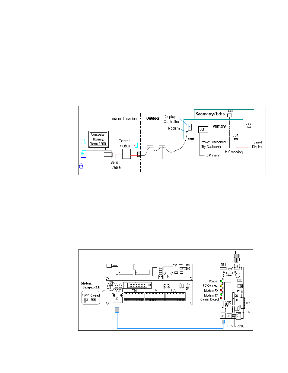
A display that is controlled using a modem requires the use of an internal or external
modem at the computer. The local phone company must provide a dedicated phone
line to the display and identify which color wire is used for “Tip” and which color
for “Ring”. The phone cable must be routed though conduit. Do not run phone line
and display power through the same conduit. Refer to
174342 for system layout.
Figure 25: Modem Display Layout
1. When connecting to the modem in the display, terminate the phone line to
TB2 on the display modem. If the phone company provided a phone
termination box in the display a straight phone cable can be connected from
the box to the J5 Phone IN on the modem board in the display.
2.
and Drawing B-177662 shows the terminal block wiring.
3. A second cable (0A-1229-0054) transfers data from J6 on the modem (0P-
1146-0003) to J3 (RS232 IN) on the controller.
4. X1 on the controller should to be closed for the controller to recognize on
bootup that a modem is being used with the display.
Figure 26: Modem Signal Termination Location
Electrical Installation
3-13