Figure 39: driver board – Daktronics AF-3197-89-RGB User Manual
Page 49
3. If the pixel strip you wish to replace is located behind the driver assembly,
label the signal cables and unplug them and the power connections on the
driver assembly and remove the four corner screws. Refer to Drawing A-
183737 for more information.
4. Remove the six wing nuts holding the pixel strip in place.
5. Gently lift the strip from the display.
6. Reverse the above procedure to install a new pixel strip.
The driver is a circuit board responsible for switching the intensity levels of the
LEDs. It is located inside the driver box and mounts on the back of the module. To
remove a driver board:
1. Open the display as described in Section 4.5.
2. Loosen the two #10 screws holding the driver cover in place.
3. Lift the cover off from the assembly. Refer to Drawing A-183737 for more
information.
4. Disconnect all power and signal connections from the driver board.
5. Remove the four #6 nuts holding the board in place.
6. Gently lift the board from the display.
7. Reverse the above procedure to install a new driver board.
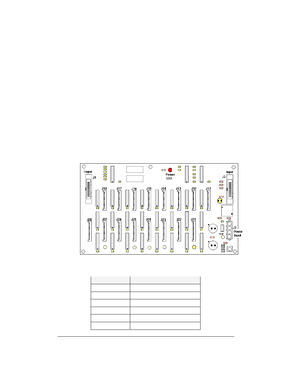
Figure 39: Driver Board
The following connectors are found on each driver board; refer to
LED/Connector
Function
J1
Signal out to next driver board
J2 Signal
in
J3
Power Input
J11-J18
Output to first row of pixel strips
J21-J28
Output to second row of pixel strips
DS1 Power
indicator
Maintenance and Troubleshooting
4-5