Figure 29: radio display controller, Figure 30: client radio connected to display – Daktronics AF-3197-89-RGB User Manual
Page 38
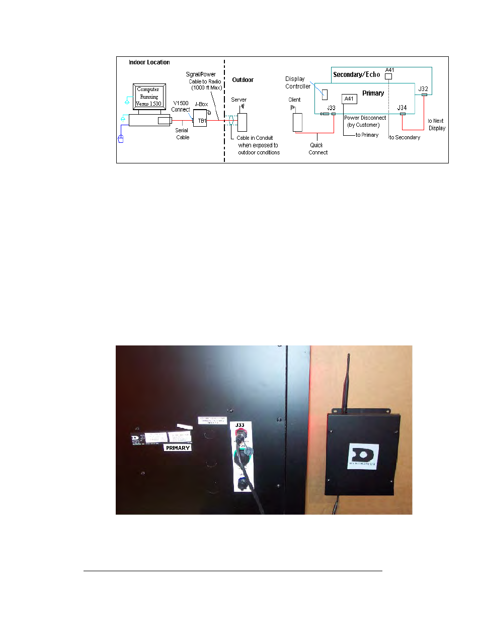
Figure 29: Radio Display Controller
1. The computer connects to the J-box/signal converter (0A-11279-0161) at
the connector labeled “V1500 PC Connect” using a DB9M to DB9F serial
cable (W-1267).
2. Use an 18 AWG, 6-conductor, cable to connect from the J-box/signal
converter to the server radio (0A-1146-0079) mounted on the outside of the
building. The cable is pinned one-to-one. (Additional drawings for the
server connections are in the Venus 1500 Radio Manual, ED13932.)
3. The client radio (0A-1146-0078) is provided with 25 feet of weather
resistant pre-terminated cable. The cable will be terminated to the display
with the quick connect plug to the top, red jack, labeled J33, on the display.
Refer to
for the quick connect termination point.
4. One end of the cable is pre-terminated to TB2 inside the radio enclosure,
and a quick connect plug is terminated at the other end of the cable. Note:
Secure any additional cable for protection from weather or vandalism.
Figure 30: Client Radio connected to Display
Electrical Installation
3-16