Daktronics AF-3197-89-RGB User Manual
Page 51
The rotary switches set the hardware address, which the software uses to identify that
particular display. When replacing a controller board, be sure to set the rotary
switches in the same address configuration as the defective controller. Each
controller in a network needs a unique address.
Note: Setting both rotary switches to address 0 (set the switches to 0 by rotating
them counter clockwise until the arrow points to 0), can activate a test mode. The
controller's power must be turned off and then turned back on to run the test mode.
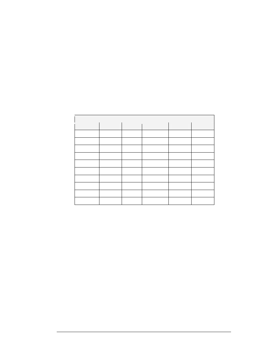
The rotary switches follow a standard hexadecimal code. The table below shows
several common addresses.
Controller Address Settings
Controller Address Settings
Address
Upper
Lower
Address
Upper
Lower
Test
Mode
0 0 10 0 A
1 0
1 11 0 B
2 0
2 12 0 C
3 0 3 13 0 D
4 0
4 14 0 E
5 0
5 15 0 F
6 0
6 16 1 0
7 0
7 17 1 1
8 0
8 … …
…
9 0 9 240 F 0
Maintenance and Troubleshooting
4-7