Daktronics nomenclature, Daktronics nomenclature -8, Figure 4: signal converter – Daktronics AF-3197-89-RGB User Manual
Page 14: Figure 5: module numbering example – 24x80 front, Figure 6: module numbering, 5 daktronics nomenclature
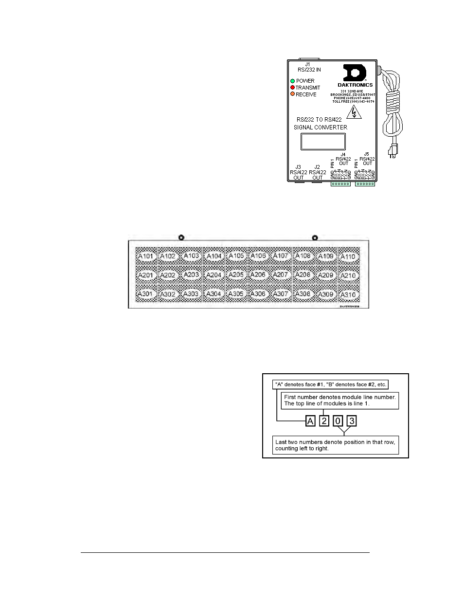
Figure 4: Signal Converter
Signal Converter: The signal converter, shown in
Figure 4, is a Daktronics supplied unit that converts
the data from RS232 to RS422. A similar looking
device is used to convert RS232 to fiber optic signal.
The signal converter is connected to the control PC via
a straight through serial cable.
Venus
®
1500: Daktronics designed, Windows
®
based
software used to create and edit messages on the
display. Refer to ED-13530 for more information.
1.5 Daktronics
Nomenclature
Figure 5: Module Numbering Example – 24x80 Front
To fully understand some Daktronics drawings, such as schematics, it is necessary to
know how those drawings label various components. This information is also useful
when trying to communicate maintenance or troubleshooting efforts.
A module is the building block of the sign.
Each module measures 8 pixels high by 8
pixels wide. By placing modules side-by-side
and on top of one another, Daktronics can
design and build signs of any size. A person
can easily remove individual modules from the
sign if required.
illustrates how
Daktronics numbers modules on a Galaxy
®
sign.
breaks down the module
numbering method.
Figure 6: Module Numbering
Introduction
1-8