Fiber optic, Fiber optic -14, Figure 27: fiber display layout – Daktronics AF-3197-89-RGB User Manual
Page 36
Fiber Optic
Reference Drawings:
System Riser Diagram, Fiber ...................................... Drawing A-174344
Schem, Sig Wiring, Internal, W/QC PCB..................... Drawing B-177662
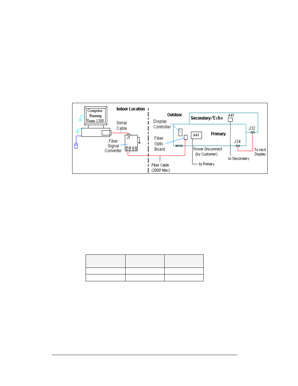
When using fiber cable, the cable will connect directly from the signal converter to
the fiber optic board in the display. Refer to
and Drawing A-174344 for
the system layout.
Figure 27: Fiber Display Layout
1. Connect the two fibers at the signal converter (0A-1127-0256) and the other
two at the fiber optic board (J4/J5) (0P-1146-0024) in the display. Always
remember to connect TX to RX and RX to TX. (Either pair of fiber outputs
on the signal converter can be used, but only the left pair of inputs on the
fiber optic board in the display.)
and B-177662 for cabling in the display.
3. A 8-conductor cable with RJ45 connectors ( 0A-1229-0054) then relays the
signal from J7 on the fiber optic board to J3 (RS232 IN) on the controller
4. The computer connects to the signal converter through a DB9 to DB25
serial cable (W-1249).
Signal Converter
to Fiber
Board
Signal
Converter
Field Cabling
Fiber Optic
Board
J2 (TX1)
(Color varies)
J5 (RX)
J3 (RX1)
(Color varies)
J4 (TX)
Electrical Installation
3-14