Fiber interconnection, Optional temperature sensor, First time operation – Daktronics AF-3197-89-RGB User Manual
Page 42: Optional temperature sensor -20, First time operation -20, 9 optional temperature sensor, 10 first time operation
Electrical Installation
3-20
Pin 4 (D2IN-N)
Green
Pin 3 (D1OUT-N)
Pin 5 (D2IN-P)
White
Pin 2 (D1OUT-P)
Pin 6 (Shield)
Pin 1 (Shield)
Note: When not using the quick connect interconnect cable; cabling must be in
conduit between displays.
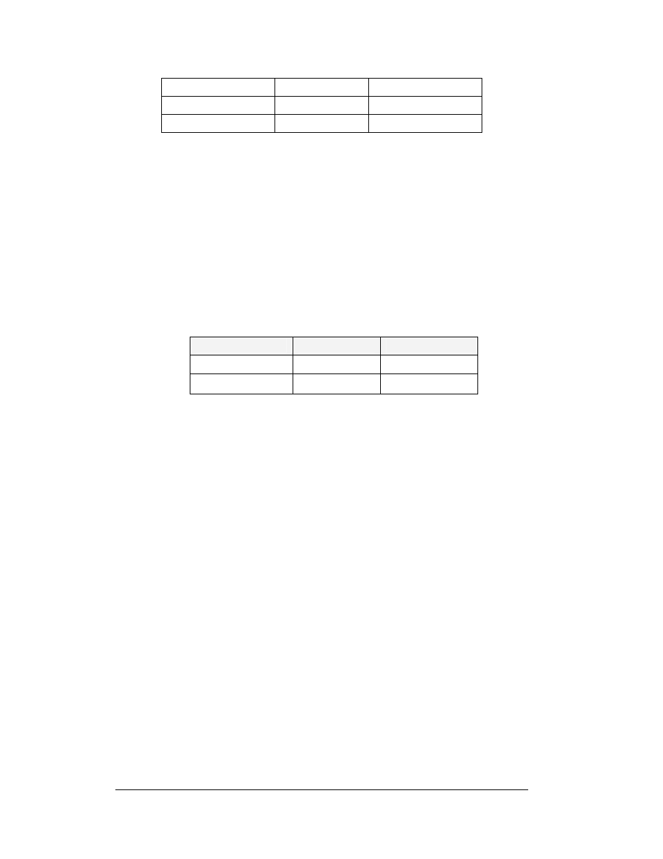
Fiber Interconnection
A four-conductor fiber cable is used in connecting two or more displays in the Fiber
Interconnection method. Two fibers will be used for the connection and two will be
saved for spares. Connect the fiber cable to the fiber cards in the displays as
described in Drawing A-174344 and in the following table. The two jacks on the left
side of the fiber optic board (J2 and J3) will be used on the first display and the two
on the right side of the board (J4 and J5) will be used in on the second display.
Always connect transmit to receive and receive to transmit.
Fiber Interconnection
Face A Data Out
Field Cabling
Face B Data In
J2 Transmit (TX1)
Color Varies
J5 Receive (RX2)
J3 Receive (RX1)
Color Varies
J4 Transmit (TX2)
3.9 Optional Temperature Sensor
If you have an optional temperature sensor to be used with your display, see
Appendix C for mounting and signal connections.
3.10 First Time Operation
Each time the display is powered up; the display will run through an initialization in
which it will display the following:
1. Product Name (Galaxy®)
2. Display Size (Row x Column)
3. Shading (64 Mono)
4. Bootloader Version (OS X.XX)
5. Firmware Number (ED13305)
6. Firmware Revision (Rev X.XX)
7. Hardware Address (HW:XX)
8. Software Address (SW:XX)
9. IP Address: ((default) 172.16.192.25)
10. Subnet Msk: ((default) Msk: 255.255.0.0)
11. COM1 Configuration (C1:V15) ((Modem C1:V15) If a Modem is present)
12. COM 2 Configuration (C2:RTD)
13. Socket 3001: (IP 3001: V15)
14. Socket 3002: (IP 3002: RTD)
15. Line Frequency (CLK: AUTO 60 Hz)