Ethernet (fiber), Figure 33: fiber ethernet layout, Figure 34: fiber ethernet signal connections – Daktronics AF-3197-89-RGB User Manual
Page 40
4. Note:
It is the customer’s responsibility to protect their network from surges
back to their network.
Ethernet (Fiber)
The controller has a default IP address of 172.16.192.25. Use this address to connect
to the primary display, and then it can be changed to an address specified by the
network administrator. Note: Ethernet signal into the display does not allow for the
normal RS422 output signal to a second primary display. This includes the both or
either the use of an interconnect cable or separate wiring between displays.
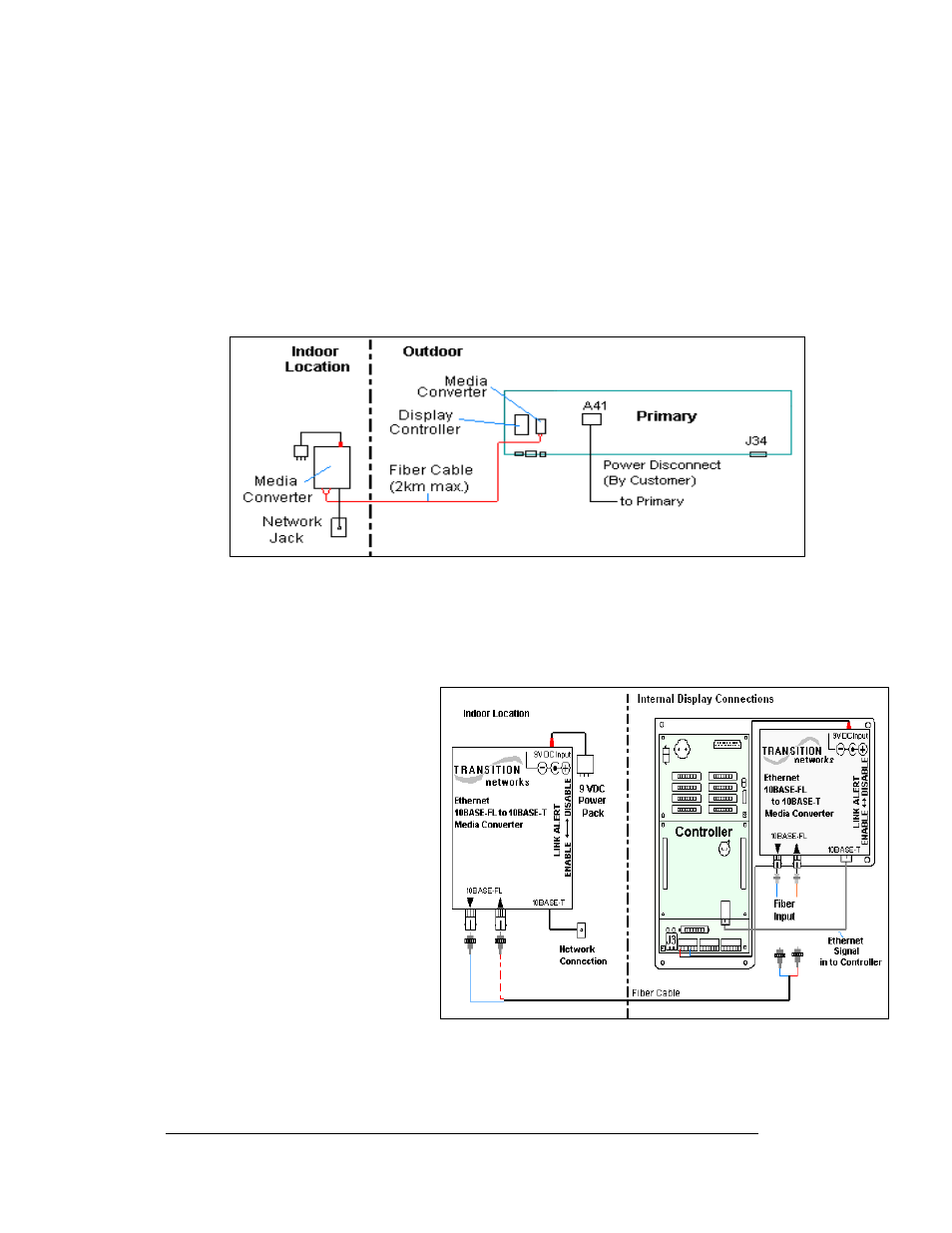
A fiber Ethernet controlled display requires the use of two media converters
connected by a fiber cable. The first media converter is connected to the network and
the second one is connected to controller in the display as shown in
A fiber Ethernet controlled
display requires the following
connections:
Figure 34: Fiber Ethernet Layout
Electrical Installation
3-18
1. A media converter (A-
1778) connects to the
network hub or switch
using an RJ45 network
cable.
2. A DC wall pack
transformer provides
power to the media
converter from a 120
VAC outlet.
3. Connect the fiber cable
from the two jacks on
the first media
converter to the two
jacks on the second media converter in the display. (Always connect
transmit on one media converter to receive on the second, and receive to
transmit.)
Figure 33: Fiber Ethernet Signal Connections