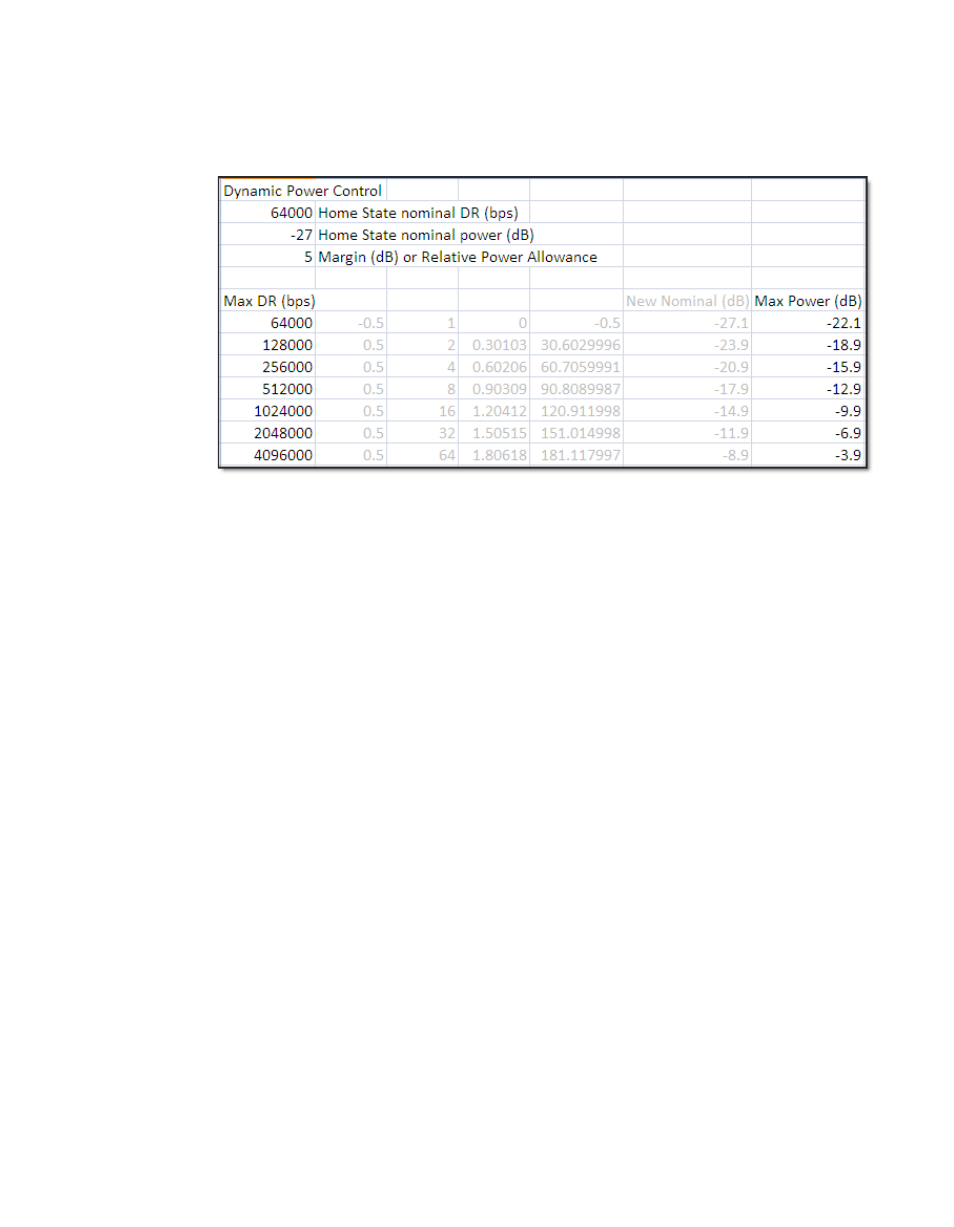
Figure c-1 data rate to power relationship, dpc – Comtech EF Data SLM-5650A Vipersat User Manual
Page 125

Appendix C - Dynamic Power Control
C-5
Description
Mbps. With a set margin of 5 dB, the additive power is never greater than the set
level at any rate, but still provides a full range of power, up to the site maxi-
mum.
Figure C-1 Data Rate to Power Relationship, DPC
Note that only base rates are used in this example, with no alternative modula-
tion or code rates.
Margins are very important because they are used to compensate for rain attenu-
ation which could be as severe as 8 dB in Ku-band frequencies. The value of the
uplink margin depends on the availability numbers set for the link. It should be
noted that the E
b
/N
0
defines the link quality threshold (target), whereas the
margin defines the link availability. The dynamically controlled margin servo-
mechanism, tracking the target E
b
/N
0,
allows the link to operate with calculated
quality during clear-sky, adjusting higher during impaired conditions or lower if
satellite EIRP or link gain increases. When link gain increases, the DPC has full
range to decrease the power to the hardware lower limit, -40 dBm (L-band), -25
dBm (IF).
Additionally, the system is required to cap or limit the site to never exceed the
budgetary power. To prevent the use of excessive power (past the saturation
point) that will drown out the signal and possibly cause damage to the satellite,
the modulator calculates a maximum power value for transmit. This control is
accomplished with the DPC command line calculator that determines the maxi-
mum achievable budgeted power (EIRP
C
) for the site. This menu driven calcu-
lator (Telnet/CLI and WSI only) allows an operator to enter site budgetary
numbers (DPC Margin, Max Data Rate, Max Code Rate, Max Modulation, and
Max FEC Type) to determine if the calibrated modulator base value output can
achieve the maximum power range, while also limiting the site to the calculated
overall Max Power.
