3 connector ‘j3 | power in’ (ac power mains), 2 lpod ps 2 ‘j3 | power in’ (ac power main) – Comtech EF Data LPOD User Manual
Page 45
LPOD C-, X-, or Ku-Band Outdoor Amplifier / Block Up Converter
MN-LPOD
System Connections, Installation and Startup
Revision 10
2–5
2.3.3 Connector ‘J3 | POWER IN’ (AC Power Mains)
WARNING! FOR SAFETY REASONS, TAKE CARE TO NOTE THAT THE ‘J3’ AC POWER
CONNECTION PIN ASSIGNMENTS FOR EACH SPOD UNIT ARE NOT THE SAME.
FAILURE TO CAREFULLY REVIEW THE INFORMATION PROVIDED IN THE SECTIONS
THAT FOLLOW MAY RESULT IN PRODUCT DAMAGE OR PERSONAL INJURY.
For all LPOD models, the prime power input requirement is as follows:
• 90-264 VAC
• 47-63 Hz
• The power supply is power factor corrected. The total power required from the prime
power supply depends on the model used. Please refer to Sect. 1.5 Summary of
Specifications.
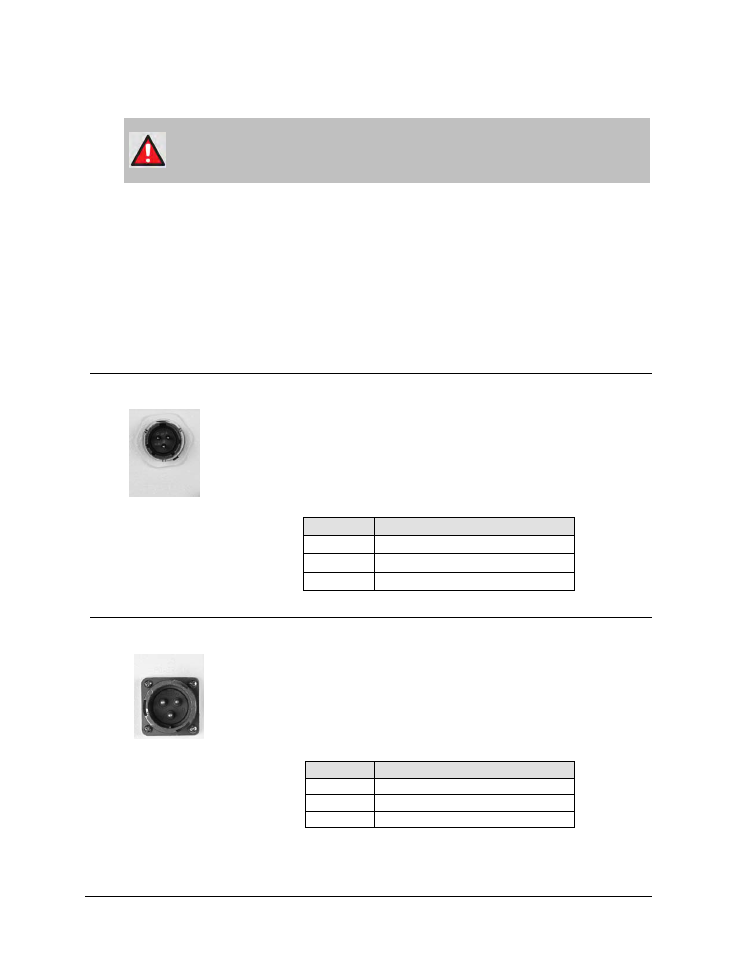
2.3.3.1 LPOD PS 1, PS 1.5 ‘J3 | POWER IN’ (AC Power Main)
The mating connector specification and pin assignments (Table 2-2) unique to the
LPOD PS 1 and PS 1.5 AC power interfaces are as follows:
Mating Connector: CEFD P/N CN/MS-STPG03F02 (ITT Cannon KPT06B-12-35).
Table 2-2. LPOD PS 1/PS 1.5 ‘J3 | POWER IN’ Pin Assignments
Pin
Description
A
LINE (L1)
B
NEUTRAL (L2)
C
GND
2.3.3.2 LPOD PS 2 ‘J3 | POWER IN’ (AC Power Main)
The mating connector specification and the pin assignments (Table 2-3) unique to
the LPOD PS 2 AC power interface are as follows:
Mating Connector: CEFD P/N CN/MS-STPG03F07 (Glenair ITS-3106F20-19SF7).
Table 2-3. LPOD PS 2 ‘J3 | POWER IN’ Pin Assignments
Pin
Description
A
GND
B
NEUTRAL (L2)
C
LINE (L1)