Fault interface specification, 5 fault interface specification – Comtech EF Data SMS-458B User Manual
Page 69
SMS-458B Modem Protection Switch
Revision 2
Theory of Operation
MN/SMS458B.IOM
4–9
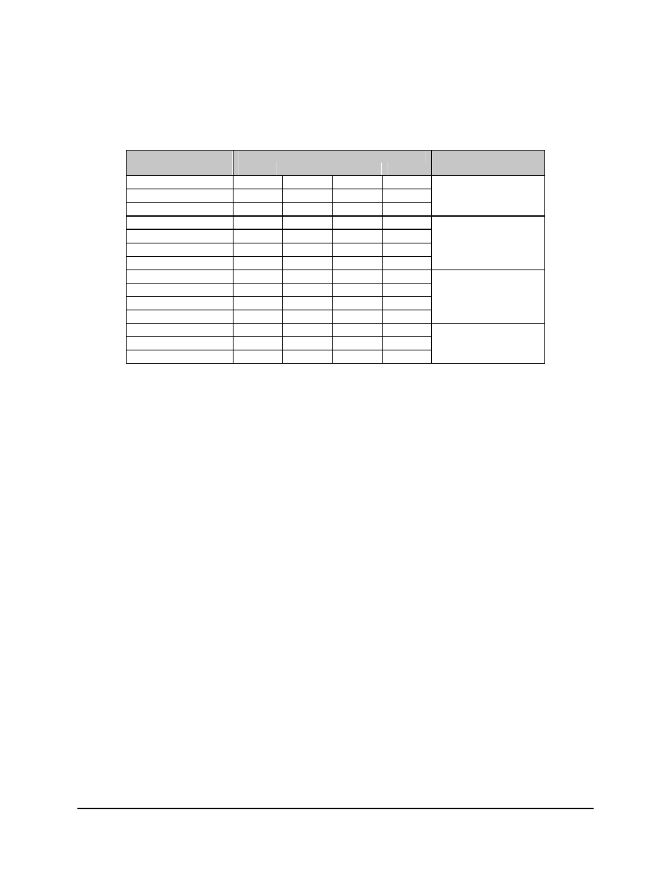
Table 4-4 shows some relay-remote command examples.
Table 4-4. Relay-Remote Command Examples
Input Lines
Command Words
Rem3
Rem2
Rem1
Rem0
Comments
START
C
C
C
C
Places the M:N in the
REMOTE
N N N C the
remote
mode.
EXECUTE
C C N N
START
C C C C Places
B/U
mod
1
B/U MOD 1
C
C
N
C
online for prime 2.
TARGET
PRIME
2
N N C N
EXECUTE
C C N N
START
C C C C Places
B/U
demod
1
B/U DEMOD 1
C
N
N
C
online for prime 4.
TARGET
PRIME
4
N C N C
EXECUTE
C C N N
START
C
C
C
C
Places the M:N in the
AUTO
N N C N auto
mode.
EXECUTE
C C N N
Notes:
1.
C = Change of state.
2.
N = No change of state.
3.
Mod = Modulator.
4.
Demod = Demodulator.
4.1.5
Fault Interface Specification
Note: These contacts report summary status. To determine the exact fault, the user must
make further inquiry, as described in Section 3.4.6.
This section defines the protocol and format structure for monitoring the fault status
interface of the switch.
The relay-remote/fault rear panel connector (J6) provides interface for fault status
information. (See Section 2.2.5 for connector location and pinout information.)
Three non-latching relays with form-C contacts show:
• Controller
status
• M:N
status
• Demodulator signal status