Relay-remote/fault (j6), 4 relay-remote/fault (j6) – Comtech EF Data SMS-458B User Manual
Page 34
SMS-458B Modem Protection Switch
Revision 2
Installation
MN/SMS458B.IOM
2–8
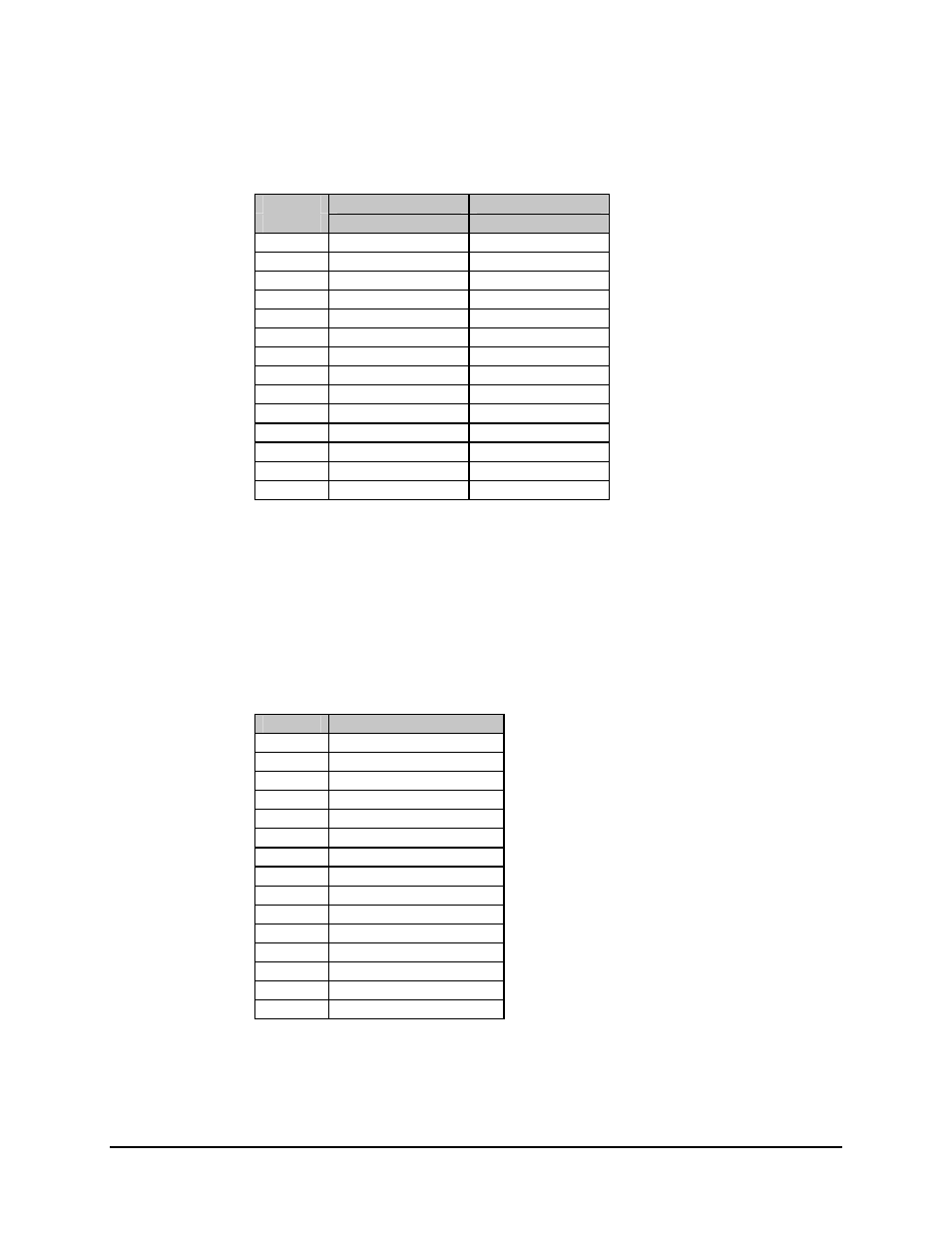
Two 25-pin female D connectors provide the online status interfaces. Screw locks
provide mechanical security for the mating connector.
J4
J5
Pin #
Name
Name
1
Mod 1 COM
Demod 1 COM
2
Mod 1 NC
Demod 1 NC
3
Mod 1 NO
Demod 1 NO
4
Mod 2 COM
Demod 2 COM
5
Mod 2 NC
Demod 2 NC
6
Mod 2 NO
Demod 2 NO
7
Mod 3 COM
Demod 3 COM
8
Mod 3 NC
Demod 3 NC
9
Mod 3 NO
Demod 3 NO
10
Mod 4 COM
Demod 4 COM
11
Mod 4 NC
Demod 4 NC
12
Mod 4 NO
Demod 4 NO
13 to 24
No Connection
No Connection
25 GND
GROUND
2.3.4 Relay-Remote/Fault
(J6)
This multi-pin connector provides both input and output signals. The inputs are contact
closures or logic level remote control inputs. The outputs are form-C relay contact
closure alarms for controller fault, M:N fault, and demodulator system fault.
The relay-remote input and fault status interface connects through a 25-pin female D
connector. Screw locks provide mechanical security for the mating connector.
Pin #
Name
1
Controller Fault COM
2
Controller Fault NC
3
Controller Fault NO
4
Relay-Remote Input 0
5
Relay-Remote Input 1
6
Relay-Remote Input 2
7
Relay-Remote Input 3
8
Demodulator Fault COM
9
Demodulator Fault NC
10
Demodulator Fault NO
11
M:N Fault COM
12
M:N Fault NC
13
M:N Fault NO
14 to 24
No Connection
25 Ground